
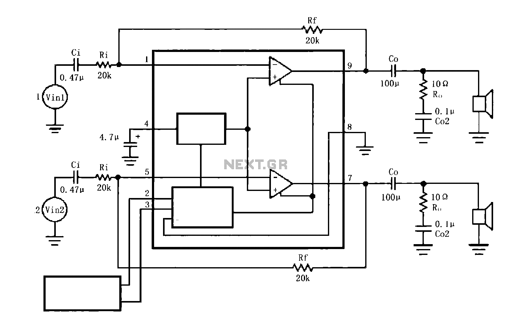
A typical circuit for the LM4916 two-channel amplifier
The LM4916 is a dual power amplifier designed for driving speakers in various audio applications. It operates from a single supply voltage, typically between 5V to 15V, making it suitable for battery-powered devices and portable audio systems. The internal architecture of the LM4916 includes a differential input stage that enhances noise immunity and improves overall sound quality.
The audio input signals are connected to the amplifier's input pins, where they are amplified by the internal circuitry. The output stage of the LM4916 is designed to drive low-impedance loads, ensuring sufficient power delivery to the connected speakers. The coupling capacitor (Co) is critical in blocking any DC offset from the amplifier, allowing only the AC audio signal to pass through to the speakers, thus protecting them from potential damage.
The external shutdown control (pin 2) is a valuable feature for power management. When not in use, grounding this pin significantly reduces power consumption, extending battery life in portable applications. The squelch control (pin 3) is equally important as it prevents audible artifacts during power-up or power-down sequences, enhancing user experience by eliminating disruptive sounds.
Overall, the LM4916 amplifier circuit is well-suited for applications requiring efficient audio amplification with minimal noise, making it a popular choice in consumer electronics, including portable speakers, televisions, and other multimedia devices. Proper implementation of the input, output, and control pins is essential for optimal performance and reliability.As shown in the figure shown for a typical circuit LM4916 two-channel amplifier. Left and right channel audio signals are input LM4916 1,5 feet, after an internal amplifier output by a 9,7 feet, after coupling capacitor Co are added to the respective speakers. LM4916 2 pin external shutdown control, when 2 feet to VDD allowed to work; prohibit work then low, reduce chip power consumption.
LM4916 3 feet squelch control, the mute mode, when the 3-pin low-level ban chip works to eliminate switching caused by "click - flapping" sound; allowed to work then high.
Related Circuits

Voltage variations and power cuts adversely affect various equipment such as TVs, VCRs, music systems, and refrigerators. This simple circuit will protect costly equipment from high and low voltages and voltage surges when power resumes. It also produces a...
Running Message Display Circuit Diagram. This circuit is based on the CD401 IC. Features: Light emitting diodes are advantageous due to their smaller size. The Running Message Display Circuit utilizes the CD401 integrated circuit, which is a versatile component in...
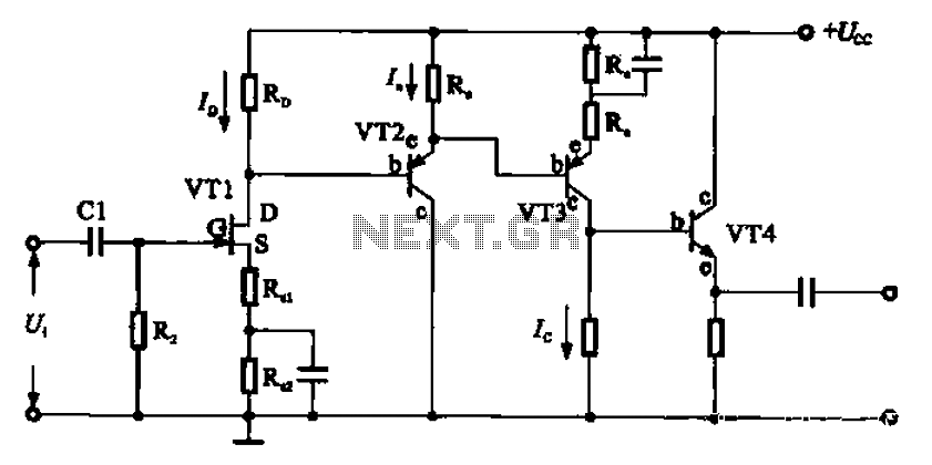
A combination of a common-source grounded emitter amplifier and a common emitter amplifier. The input impedance of the common emitter amplifier is in the range of 1.03 fl. Directly connecting the FET drive can be challenging; however, utilizing an...
The amplifier drives a pair of loudspeakers using two LM3876 integrated power amp ICs (50 watts per channel), or a pair of headphones via a Meier crossfeed filter and an OPA2134 dual opamp. It provides four switchable line level...

A gyrator is a circuit that utilizes active devices and transistors to emulate an inductor. In this instance, the gyrator comprises a transistor in conjunction with resistors R1, R3, and capacitor C2. Alternatively, a unity gain operational amplifier could...
Schematic diagram and description of a 2-watt audio amplifier circuit using the TDA7052 amplifier IC. This is a very simple audio amplifier circuit. The 2-watt audio amplifier circuit utilizing the TDA7052 integrated circuit (IC) is designed for basic audio amplification...