
With the Ability to trigger a megger thyristor circuit
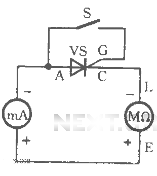
The thyristor circuit diagram serves as a fundamental component in various electronic applications, particularly in power control and switching. A thyristor is a four-layer semiconductor device that functions as a switch, allowing current to flow only when it is triggered by a gate signal.
In the circuit diagram, the configuration typically includes the thyristor connected in series with a load and a power source. The gate terminal is connected to a triggering circuit, which can be a simple resistor-capacitor (RC) network or a more complex microcontroller output. The triggering mechanism is crucial as it dictates the timing and duration for which the thyristor conducts.
When the gate receives a sufficient voltage, the thyristor enters its conductive state, allowing current to flow through the load until the current drops below a certain threshold, at which point the thyristor turns off. This characteristic makes thyristors suitable for applications such as light dimmers, motor speed controls, and overvoltage protection systems.
The triggering table referenced in the description likely contains critical parameters such as gate voltage, trigger current, and the corresponding load conditions necessary for reliable operation. Understanding these parameters is essential for designing effective thyristor-based circuits, ensuring they operate within specified limits to prevent failure or damage to the components involved.
In summary, the thyristor circuit diagram and its triggering capabilities are integral to the effective control of electrical power in various applications, providing both efficiency and reliability when properly implemented.As shown by the table to check the ability to trigger the thyristor circuit diagram:
Related Circuits
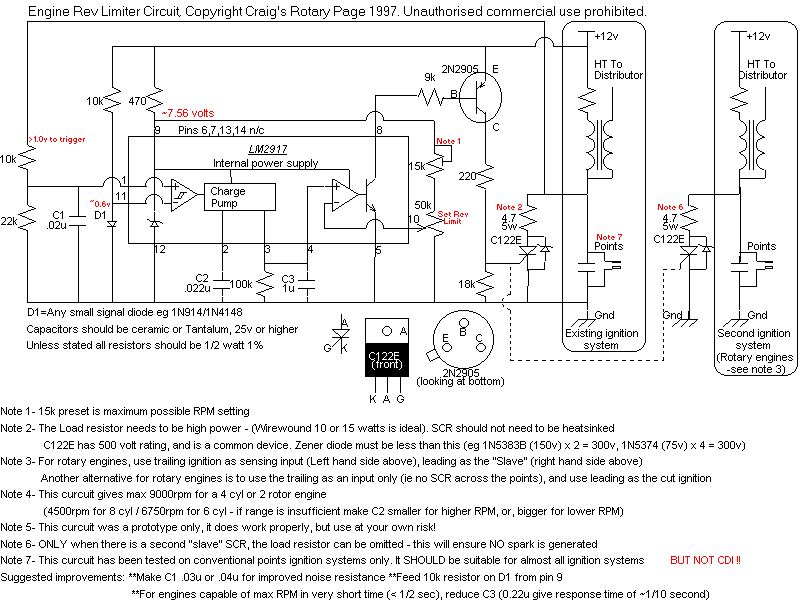
It is based on an LM2917 and an SCR, which has the advantageous characteristic of preventing mis-timed sparks, a highly desirable feature for high-output rotary engines. When the engine reaches the rev limit during acceleration, the transition is smooth...

The circuit's current exceeds the load carried by the rated current meter, prompting the user to immediately cut off the power supply to address the overload. Pressing the reset button restores power, making the system simple, convenient, and practical....

This is a simple VE7GC Popcorn RF preamplifier designed by Dick Pattinson. The circuit features a single tuned circuit at the input stage, allowing direct connection to a mixer or product detector in a straightforward receiver project. Adjustable RF...

This design is based on a publication by Milan Lulic in the German magazine elektroModell. Lulic's design utilizes surface mount technology (SMT), while this version employs standard off-the-shelf components, making it more accessible for hobbyists. For those interested in...
The circuit functions as a frequency modulation (FM) transmitter that operates within the 76 to 90 MHz FM radio band, commonly referred to as a wireless microphone. It receives signals through an FM radio receiver. The circuit is capable...
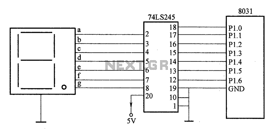
After the SCM execution, the Pl output port connects to the bidirectional input of 74LS245 driver chips. This driver operates during each phase of digital control, based on the information from the Pl port. The purpose is to convert...
Warning: include(partials/cookie-banner.php): Failed to open stream: Permission denied in /var/www/html/nextgr/view-circuit.php on line 713
Warning: include(): Failed opening 'partials/cookie-banner.php' for inclusion (include_path='.:/usr/share/php') in /var/www/html/nextgr/view-circuit.php on line 713