
Before power is in the hold state holding brake one circuit
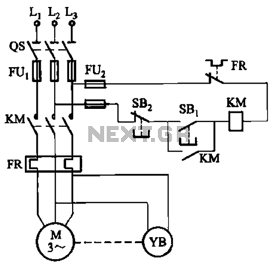
The electromagnetic holding brake circuit operates through a solenoid mechanism that integrates seamlessly with the motor control system. The solenoid, designated as YB, serves as the primary actuator that controls the engagement and disengagement of the brake system. When the motor receives power, the solenoid coil is energized, creating a magnetic field that pulls the armature connected to the brake lever. This action lifts the brake lever, thereby retracting the brake shoes away from the wheel, allowing the motor to run freely.
The system is designed to ensure safety and efficiency. The brake shoes are held in a disengaged position during normal operation, but upon de-energizing the solenoid—typically initiated by the pressing of the stop button (SB2)—the magnetic field collapses. This results in the immediate release of the solenoid's hold on the brake lever, allowing the brake shoes to be forced back into contact with the wheel by a spring mechanism. This rapid engagement of the brake shoes effectively stops the motor, preventing any unintended motion and ensuring a controlled halt.
To enhance the reliability of the system, components such as the solenoid must be rated for the specific voltage and current requirements of the motor. The use of a robust spring mechanism is also critical, as it must be capable of providing sufficient force to engage the brake shoes quickly and effectively. Additionally, the circuit may include safety features such as fuses or circuit breakers to protect against overload conditions, ensuring the longevity of the components involved in the electromagnetic brake system.
In summary, the electromagnetic holding brake circuit is a vital component in motor control applications, providing a reliable means of stopping and holding the motor in place when necessary. The design and implementation of this circuit require careful consideration of the electrical and mechanical components to ensure optimal performance and safety. Circuit shown in Figure 3-121. The key component of electromagnetic holding brake is an electromagnetic brake brakes, brake solenoid which is mainly composed of two parts iron and shoe brake components. When the motor access to power, electromagnetic brake coil YB also was electric pull, forcing the brake lever is moved upward, from leaving the wheel brake and release the brake shoes on the brake, the motor running. When the motor power supply is cut off (press the stop button SB2) when, YB also missing, and released under the action of the brake shoes so that the spring force of the rapid wheel brake, the motor quickly stopped.
Related Circuits
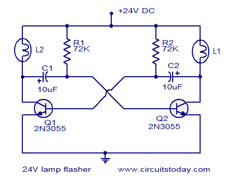
The circuit operates on 24V DC and is designed to alternately flash two 24V bulbs. It functions as an astable multivibrator with a frequency of 1Hz and a duty cycle of 50%. The lamps to be flashed are connected...
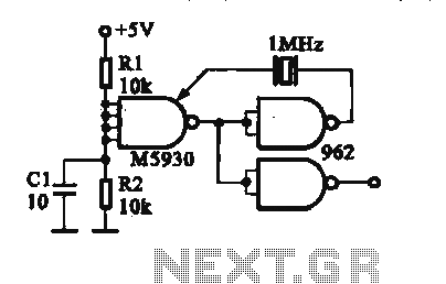
A crystal oscillator is implemented using a DTL (Diode-Transistor Logic) integrated circuit. The oscillation frequencies are 100 kHz and 1 MHz. The circuit consists of a gate circuit that generates a signal for the oscillator circuitry in DTL. The crystal...
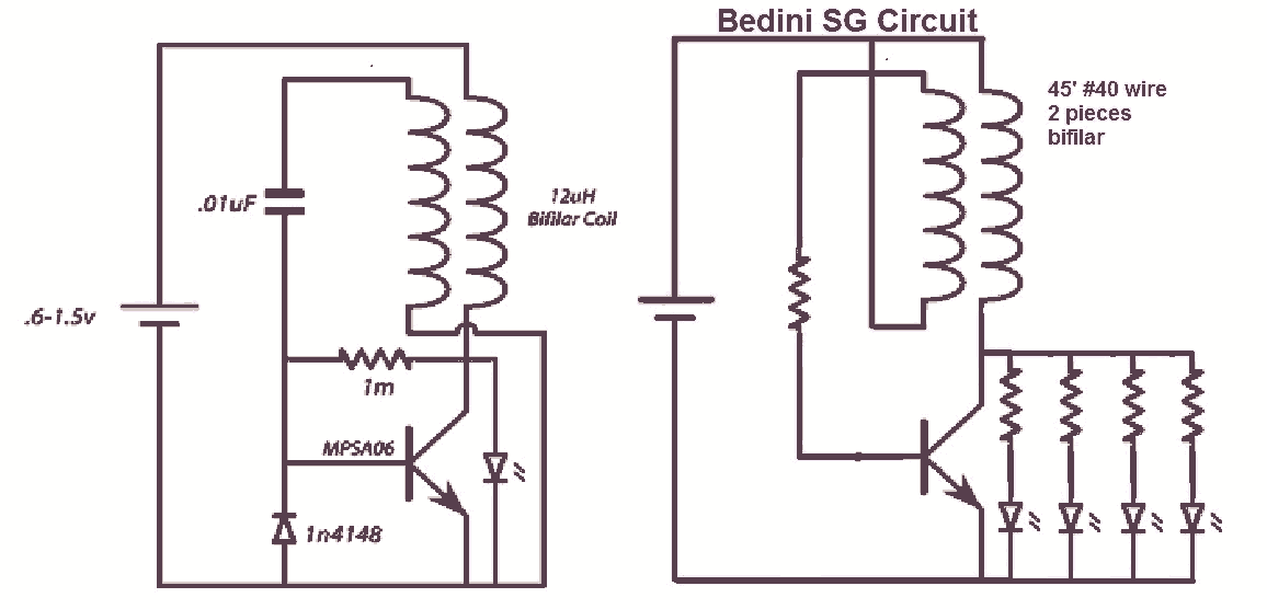
It would be beneficial to obtain schematics of the Joule Thief and Bedini oscillator circuit connections. This is an area that has not been previously explored. The schematic on the left was sourced from the Energetic Forum, while the...

The circuit below demonstrates the generation of a single positive pulse that is delayed in relation to the trigger input time. It is similar to a previously described circuit but utilizes two stages, allowing for control over both the...
The south circuit consists of four parts, arranged in descending order: an NPN transistor dynamic garbage device (T1), a PNP transistor differential amplifier (T2, T3) forming a double differential circuit, two balanced output amplifiers with opposite phase, and a...

This is a design circuit for a low-cost FM antenna booster that can be used to listen to programs from distant FM stations clearly. The antenna FM booster circuit comprises a common-emitter tuned RF preamplifier wired around the VHF/UHF...