
1850 Watts free energy power
Warning: Undefined array key "extension" in /var/www/html/nextgr/view-circuit.php on line 468
Deprecated: strtolower(): Passing null to parameter #1 ($string) of type string is deprecated in /var/www/html/nextgr/view-circuit.php on line 468

There is also concern about the configuration of the coil, with doubts expressed about whether it is connected as a Tesla bifilar coil. Stefan's objection highlights that readings taken at the peak of the outer envelope could be misleading, as these cookers utilize envelope modulation to control cooking depth. Analysis of the envelope-modulated waveform indicates that the true average output power is likely to be about half of the peak measurements. It is suggested to capture simultaneous waveforms from both the transmitting and receiving coils in the cooker to compare their performance. It has been noted that the envelope modulation is evident, and computed power outputs align well with light meter results. The next step involves measuring the output coil of the induction cooker directly and recalculating power using consistent scope settings, while also expanding the timebase to observe multiple cycles of the modulation envelope for a more accurate power curve.
The circuit description involves a differential measurement technique utilized to extract the voltage across a Current Sense Resistor (CSR). The CSR plays a crucial role in monitoring current flow in various applications, and the accuracy of this measurement is paramount. The differential approach allows for the identification of voltage drops across the CSR, which is essential for assessing the current flowing through it.
At the operating frequency of approximately 33 kHz, the characteristics of the circuit become critical. The inductance of 500 nH, equivalent to a length of 15 inches of wire, introduces a potential error in current measurement. This inductance, although seemingly negligible, can significantly affect the accuracy of the readings due to its series resistance impact. The presence of inductive elements in the current sense loop can lead to erroneous interpretations of the current flowing through the CSR.
The measurement setup is another vital aspect of this circuit. Proper probe placement directly across the CSR is necessary to ensure accurate voltage readings. Any deviation from this could result in additional voltage drops being included in the measurement, leading to incorrect conclusions about the current flow. Therefore, careful examination of the probe configuration is essential.
Furthermore, the circuit's response to envelope modulation in induction cookers is noteworthy. The modulation technique employed in these systems is designed to optimize cooking efficiency by adjusting the power output based on the cooking depth required. The analysis of waveform characteristics is crucial to understanding how effectively the system operates and how power is distributed over time.
In addition, capturing simultaneous waveforms from both the transmitting and receiving coils provides insight into the overall system performance. This comparative analysis allows for a better understanding of the efficiency of energy transfer within the system and highlights any discrepancies in power calculations.
Ultimately, recalibrating the measurement settings to account for the modulation envelope will yield a more accurate representation of the power output, allowing for improved performance assessment of the induction cooker system. This comprehensive approach ensures that all variables are considered, leading to a more reliable and accurate current measurement in the circuit.Calculates the difference between the two waveforms to arrive at what he believes is the voltage across the CSR. At the 33Kc or so frequency of the positive going voltage peak (calculated from time interval at FWHM), around 500nHy of inductance in the current sense loop would produce a 100% error in the current measurement (i.
e. , it would add add. 1 ohms in series with the. 1 ohm CSR), despite the CSR being non-inductive. 500nHy is equal to about 15 inches of straight wire. If I am in error regarding my assumptions related to his use of the CSR and how he measured the voltage across the CSR, please feel free to enlighten me. Possibly someone can take a closer look at his photo and see if he does indeed have his probe and probe ground directly across the CSR.
From what I can see zoomed in, it does not appear so. I may be incorrect, but it appears from the various scope shots and photos that he is not measuring directly across the CSR (I cannot see a scope gnd lead attached to the CSR), but is instead measuring voltage at two points, with one point including the CSR Vdrop. It appears that he then calculates the difference between the two waveforms to arrive at what he believes is the voltage across the CSR.
At the 33Kc or so frequency of the positive going voltage peak (calculated from time interval at FWHM), around 500nHy of inductance in the current sense loop would produce a 100% error in the current measurement (i. e. , it would add add. 1 ohms in series with the. 1 ohm CSR), despite the CSR being non-inductive. 500nHy is equal to about 15 inches of straight wire. If I am in error regarding my assumptions related to his use of the CSR and how he measured the voltage across the CSR, please feel free to enlighten me.
Possibly someone can take a closer look at his photo and see if he does indeed have his probe and probe ground directly across the CSR. From what I can see zoomed in, it does not appear so. However. I am not convinced that the coil is hooked up as a Tesla bifilar ! It`s not clear to me just how the coil is hooked to the lead-out wires. But I`ll take his word for it for now. Stefan`s objection- that the readings are taken at the peak of the outer envelope- seems very damning.
These cookers use the envelope modulation to control depth of penetration into the cooking pan (see the pdf). It`s pretty clear from looking at the envelope-modulated waveform Stefan linked and those in the pdf file that the true overall average output power is going to be about half of that measured at the very peak of the envelope.
I`d like to see simultaneous waveforms from both the transmitting coil in the cooker, and the receiving coil. I will guess that the _transmitting_ coil in the cooker will show the same high "efficiency" when measured by the same method used for the receiving coil.
ETA: Yep, it`s perfectly clear from the video that the envelope modulation is happening, and that Jean-Louis has computed his power output from the peak oscillations. Results are in very good agreement with the lightmeter result. Now the issue is tracking down the reason for the unusually high figure from the scope measurements. Again, I suggest measuring the induction cooker`s output coil directly and computing its power using the same scope settings as before.
Then, "zoom out" the timebase and trigger the scope on the modulation envelope, showing two or three full cycles of the envelope, and let the scope recompute the power curve over a more realistic time interval, one which doesn`t just count the peak values within one "fat" part of the envelope, but rather counts several cycles of the modulation enve 🔗 External reference
Related Circuits
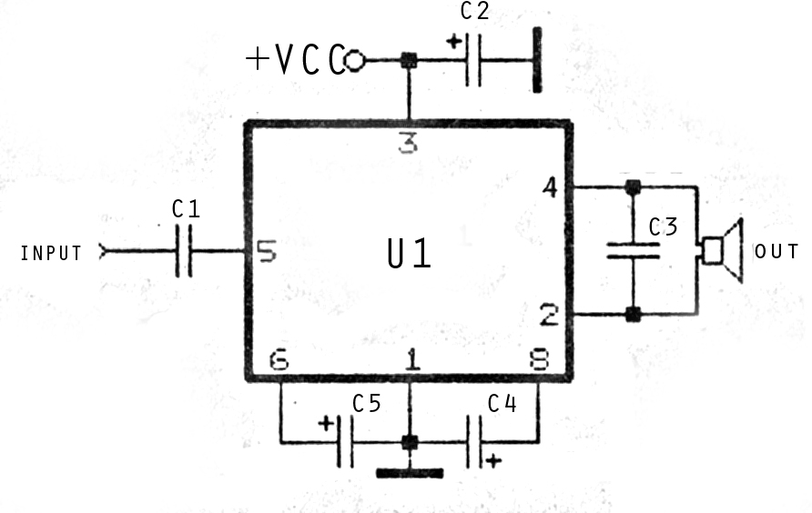
The image above depicts a miniature audio amplifier that is quite simple in design. A schematic for this audio amplifier is provided, which requires only a few components, as detailed in the accompanying diagram. This amplifier is inexpensive to...
The first section of the 555 timer is configured as an astable oscillator, with resistors R2 and capacitor C1 determining the frequency. The output is available at pin 5. The second section is set up as a phase inverter,...
New cellular phones have incorporated high-resolution cameras that require bright illumination of the surrounding area to achieve high-quality pictures. Traditional xenon-filled photo flashes cannot be used due to the limited space available in cellular phone cameras. Instead, design engineers...
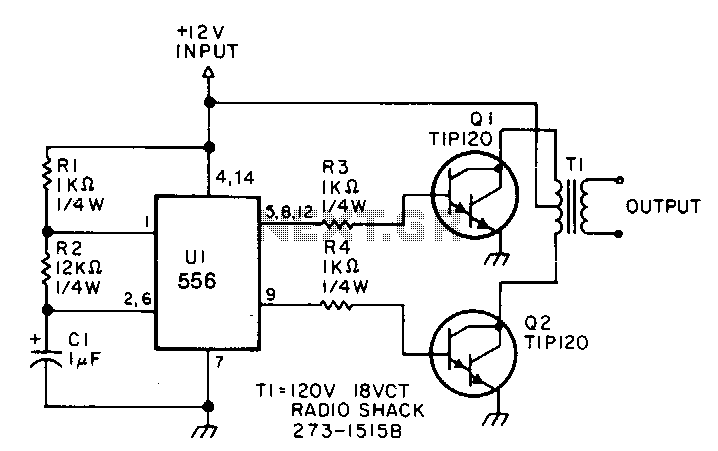
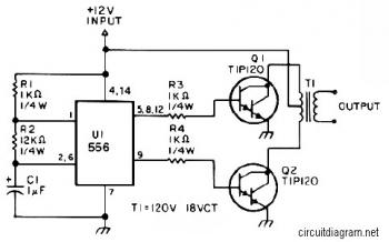
This low-power inverter utilizes only nine components to convert 10 to 16 VDC into a 60 Hz, 115 V square-wave output suitable for operating AC equipment with a maximum power of 25 W. The initial section of the 556...
A 150W power amplifier circuit diagram utilizing power transistors TIP41, TIP142, and TIP147. The design is straightforward enough to construct without a printed circuit board (PCB). The power output range is approximately 100-150W. The 150W power amplifier circuit is designed...

The circuit of the transmitter is depicted in Figure 1, showcasing its simplicity. The initial stage is the oscillator, which is tuned using a variable capacitor. To select an unused frequency, adjust C3 carefully until background noise ceases (the...