
mini and simple power amplifier

The miniature audio amplifier circuit described is an efficient solution for low-power audio applications, suitable for portable devices or small audio projects. The S1513 integrated circuit serves as the core of the amplifier, providing amplification with minimal additional components, thereby simplifying the design and reducing costs.
Key specifications of the S1513 include its low supply voltage requirements, allowing it to operate effectively with battery power, making it ideal for mobile applications. The output power of 0.1 watts is sufficient for driving small speakers or headphones, producing clear audio without significant distortion.
The basic components of the circuit typically include the S1513 IC, resistors for setting gain and biasing, capacitors for coupling and decoupling, and possibly a potentiometer for volume control. A power supply circuit is also necessary to provide the required voltage range.
The schematic layout should be carefully followed to ensure proper connections and functionality. The power supply should be decoupled with capacitors to filter out noise, ensuring stable operation. Additionally, the output stage must be connected to a suitable load, respecting the specified impedance to prevent damage to the circuit.
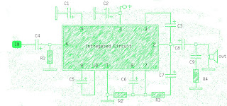
This audio amplifier circuit exemplifies a straightforward approach to audio amplification, making it an excellent choice for hobbyists and engineers seeking to create compact audio solutions with minimal complexity.What is the meaning of the picture above The above picture is a miniature audio amplifier and very simple. Here I will give an audio amplifier schematic is very simple which only requires a few components only, can be seen under this scheme.
See from above scheme may occur to you, certainly cheap enough to make this amplifier and quite easy to ma ke. The above simple audio amplifier circuit using an IC as the main amplifier and accompanied by other components. IC used is S1513, which requires a supply voltage ranging from 1. 5 volts to 6 volts. And only 0. 1 W output power with 4 ohm impedance. For a list components can be seen below. 🔗 External reference
Related Circuits
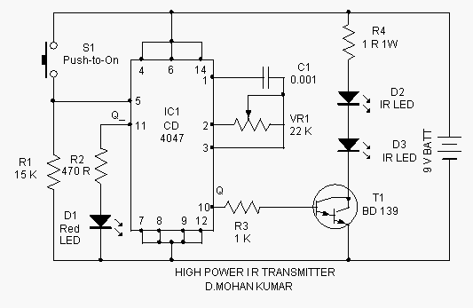
This infrared transmitter is capable of activating IR-based switching circuits from a distance of 10 meters or more. It features a high-power IR transmitter that drives two infrared LEDs. The infrared transmitter circuit is designed for remote activation of devices...
This is a simple circuit that does the day/night switchings you have in mind. POT1 is used to set the light level at which the circuit switches from enable to disable. The described circuit functions as an automatic day/night switch,...
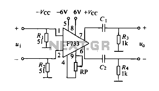
The F733 integrated wideband amplifier is a common-emitter configuration that features a total wideband amplifier with an internal feedback circuit. It is compact, offers zoom capability, and exhibits excellent circuit stability. The F733 circuit, as illustrated in the accompanying...
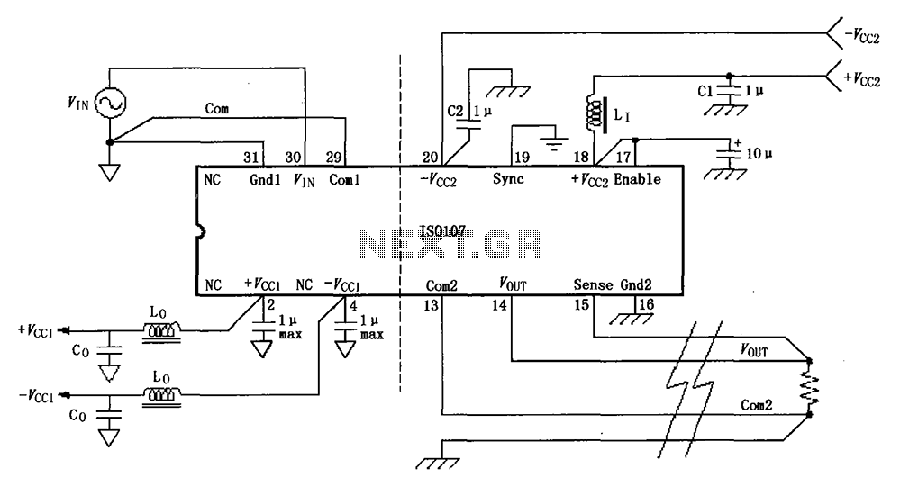
The basic connection circuit for the ISO107 signal and power supply is illustrated. Each power supply terminal must include a bypass filter. If the output current from the isolated power supply exceeds 15 mA, it is advisable to utilize...
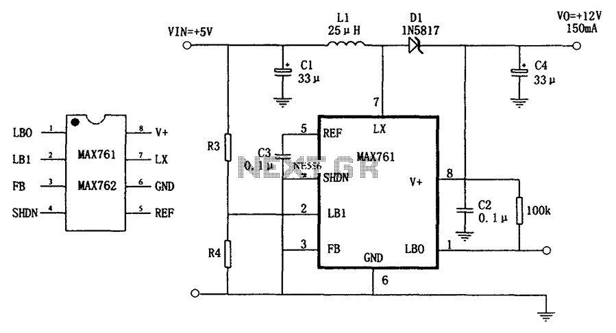
The circuit depicted in the figure illustrates an efficient, low-power step-up DC-DC converter, the MAX761, along with a few external components, which functions as a +5V to +12V boost power supply. Its characteristics include a conversion efficiency of 86%...
The amplifier circuit is well-suited for use in subwoofer speakers due to its robust performance. This circuit utilizes an integrated circuit (IC) based on the STK series. It can be employed in vehicles equipped with speakers or a subwoofer...