
Electronic Fuse for DC Short Circuit Protection

This circuit operates as a protective mechanism for power supplies and batteries, primarily focusing on preventing damage due to short circuits. At the core of this circuit is a relay, which acts as a switch that opens or closes the circuit based on the presence of a fault condition. When a short circuit occurs, the relay is activated, thereby interrupting the flow of electric current and protecting the power supply or battery from potential damage.
The selection of the relay is critical; it must have a voltage rating that matches the input voltage of the circuit to ensure reliable operation. The inclusion of a 100µF capacitor is also vital, as it helps to stabilize the voltage and filter out any high-frequency noise that may affect the performance of the circuit. If a 100µF capacitor is not available, a C106 component can serve as a substitute for the BRX46, although it is advisable to verify compatibility with the circuit's specifications.
For current regulation, a 10K potentiometer can be integrated into the design. This allows for fine-tuning of the current flowing through the circuit, catering to different operational requirements. In scenarios where a fuse is employed to handle higher currents, adjustments to the 0R6 5W resistor are necessary. The resistance value may be lowered to 0R47, 0R33, 0R22, or even 0R1, depending on the specific current requirements. Furthermore, the power rating of the resistor must be increased to accommodate the higher energy dissipation that may occur under these conditions.
Overall, this circuit design emphasizes the importance of component selection and configuration to ensure effective protection of power supplies and batteries in various applications. Proper implementation will enhance the reliability and longevity of the electronic system.This circuit will protect your power supply or battery. The electric current will stopped by relay when electric current short occured, Relays must be chosen with a voltage value equals to the input voltage. Don`t omit using the 100uF capacitor with appropriate voltage value with respect to the input voltage.
If you can`t provide, you can use C106 instead of BRX46. You can adjust the current with using 10K potentiometer. If you will use the fuse with very high currents, lower the 0R6 5W resistor value (ex. 0R47, 0R33, 0R22 or 0R1). Watt value of the resistor should be increased also. 🔗 External reference
Related Circuits
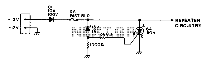
To protect portable emergency power repeaters from reverse or excessive voltage, diode D1 prevents damage from incorrect polarity, while the zener diode voltage sets the maximum voltage that can reach the rest of the circuitry. Additionally, a fast-blowing fuse...

A DC booster circuit is illustrated in the figure, which represents a step-up transformer circuit diagram. The step-up transformer (T) can be utilized to power small transistor radios. The winding ratio can be adjusted to achieve the desired output...
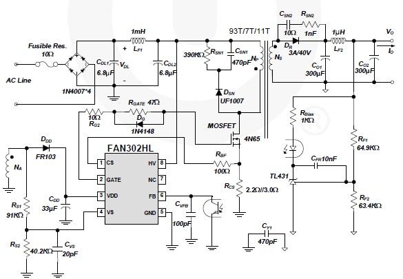
A simple 5-volt switching power supply electronic circuit project can be designed using the FAN302HL, a highly integrated PWM controller integrated circuit. This IC provides several features that enhance the performance of general flyback converters. The constant-current control of...
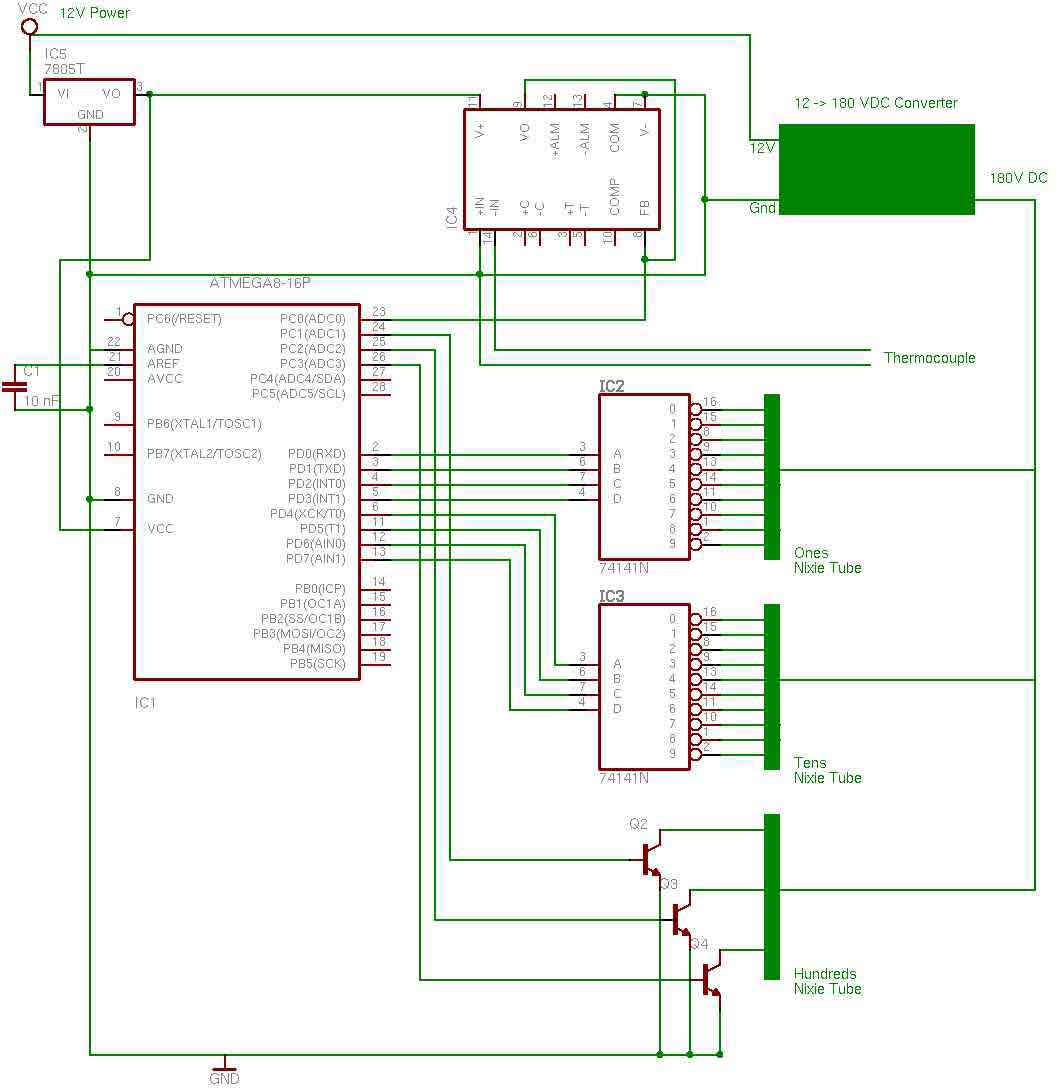
the entire circuit is comprised of integrated circuits. This makes for some easy organization when it goes to the circuit board for soldering. In addition, I used only 3 of the pins on the 3rd nixie tube for the...
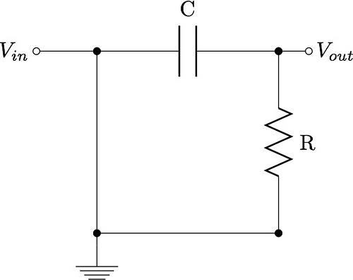
This guide aims to demonstrate the construction of various filter circuits, specifically low pass and high pass filters, along with additional details. The construction of filter circuits is essential in many electronic applications, as they allow for the selective passage...
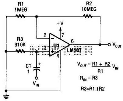
A general-purpose noninverting AC amplifier for audio and other low-frequency applications is presented. Design equations are included in the figure. Almost any general-purpose operational amplifier can be utilized for U1. The circuit configuration features a noninverting amplifier topology, which is widely...