
1kHz precision sine generator using PIC 16F628
The schematic for this circuit includes the following components:
1. **PIC Microcontroller (PIC 16F628)**: The microcontroller serves as the core of the circuit, generating the sinewave output based on the programmed sine table.
2. **Crystal Oscillator (20 MHz)**: Provides a stable clock frequency for the microcontroller, ensuring accurate timing and frequency generation.
3. **5V Voltage Regulator**: Supplies the necessary power to the microcontroller and associated components.
4. **Trimmer Capacitor**: Used to fine-tune the crystal oscillator frequency for precise output.
5. **Resistors and Capacitors for Filtering**: A combination of resistors and capacitors is used to create a low-pass filter, with specific values adjusted to achieve the desired sinewave characteristics while minimizing distortion.
6. **Inductor (2.3 mH)**: Introduced in the filtering stage to further reduce high-frequency noise without compromising the sinewave shape.
The circuit design emphasizes simplicity and effectiveness, making it suitable for hobbyist applications and calibration testing where a precise sinewave is required. The careful selection of components and tuning ensures that the output remains stable and accurate, fulfilling the necessary specifications for various applications.This is a very simple circuit where the PIC and an internal 1kHz sinewave table do all the hard work of making an accurate sinewave. Then it needs only a few external parts for filtering. The sinewave has a very high frequency accuracy as it is generated from a xtal. And with appropriate filter parts the sinewave is quite low in distortion. This m akes the device useful for calibration testing and any use where you need a mathematically correct sinewave of a very precise fixed 1kHz frequency. The sine table was created in Excel spreadsheet and makes a sine ranging from PWM 14 to PWM 86, a total PWM amplitude of 73% which is accurately distributed around the mid voltage point of 50% PWM.
The sinewave was deliberately made at this amplitude to get the best performance out of the PWM system. The sinewave has some tiny error in each sample, but every sample has been rounded up or down to the closest PWM value to a perfect sine.
The max error for any sample is less than 0. 68% of the sine amplitude. Hopefully this will not matter in the final operation as the important thing is the overall shape of the sinewave, because all the tiny PWM errors will be easily integrated out by the hardware filter. A PIC 16F628 was set up with nothing more than a 5v regulator and 20MHz xtal (and a few PSU caps etc).
A trimmer cap was used to trim the 20MHz xtal to better than 1 PPM against my GPS tuned frequency meter. This means the 1kHz output will be 1000. 000Hz (+/-0. 001Hz). The PWM output from PIC pin RB3 was filtered through a 1k trimpot and 0. 22uF cap. The trimpot was adjusted to about 800 ohms, and the output of the filter is shown below on the scope; The sine wave is about 3v amplitude peak to peak.
You can see the 50kHz PWM frequency as the fine sawtooth "hash". But importantly, the overall shape of the sine looks quite good and the tiny differences in each of the sine table enries look to have already been smoothed out. Checking some online "low-pass filter calculators" showed that inductor values would be quite large and these inductors might not be very accessible for a simple hobby style build.
So I fiddled with some RC values in an attempt to get a good 2v p/p sinewave. I tried to keep the first stage impedance low, but 330 ohms to 0. 33uF was about as low as I could go without causing some distortion from drawing too much current from the PIC output pin. Then the other 2 stages tried to keep total impedance low by keeping the resistor values low, and used just enough capacitance to get rid of the 50kHz PWM hash while hopefully having very little effect on the sine shape or amplitude.
And here are the waveforms comparing point B with the final output at point C (2. 0v p/p). Afterward I zoomed the `scope right in but can`t detect any 50kHz freq in the final output. Unfortunately I don`t have a distortion meter to measure just how good the output sine wave is made by such a simple filter. But when I adjusted the amplitudes on the `scope to be the same, the 3 sine waveforms appear to be exactly the same shape as each other, which is a good sign (good sine haha).
I don`t have many inductors in the mH size range apart from some cheap miniatures that are a bit nasty. However I did find some decent sized 1. 15mH toroids in my old stock. I added 2 in series (to make a 2. 3mH inductor) in the first filter stage. This reduced the 50kHz hash at point A by about 60% compared to the same filter without the inductor.
Which was quite nice and better still had practically no visible effect on the sine wave shape. I did notice all the amplitudes went up a couple of percent I assume this is because the currents out of the PIC pin are reduced due to the inductor so the PIC output pin FETs are able to produce a few percent more average voltage. As I saw previously reducing the current loading on the PIC output improved the sine shape so this is a good thing.
Above are the waveforms at points 🔗 External reference
Related Circuits
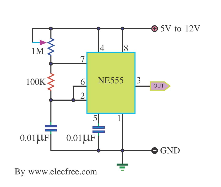
This is a simple pulse generator circuit or standard astable oscillator circuit for the IC 555 timer, NE555N IC. The astable oscillator circuit utilizing the NE555 timer IC serves as a versatile pulse generator, producing a continuous square wave...
This design outlines a simple 1 kHz square wave generator utilizing a few components and the LM3909 integrated circuit, which is beneficial for testing audio equipment. The circuit operates on a single 1.5V battery cell, producing a maximum output...
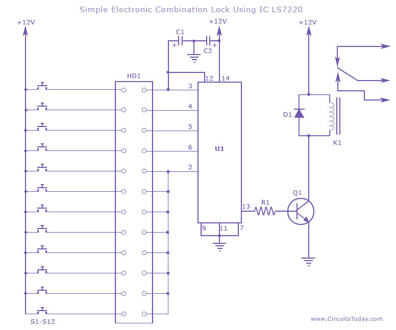
This circuit diagram illustrates a simple electronic combination lock utilizing the IC LS7220. It is designed to activate a relay for controlling any device (on & off) when a specific combination of four digits is entered. The circuit operates...
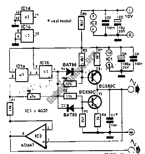
Converting periodic waveforms to square waves is essential for extracting clock signals from data, creating waveform generators, and developing timing-pulse generators. A square-wave conversion circuit is more advantageous when the duty cycle of the square wave is variable and...
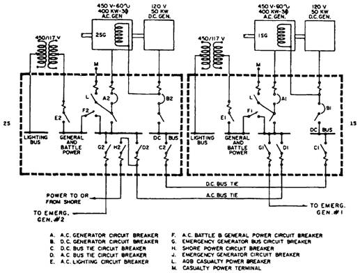
A single-line diagram of the ship's service generator and switchboard connections for a destroyer. Components include a resistor, capacitor, transistor, and others. The single-line diagram serves as a simplified representation of the electrical connections and components within the ship's service...
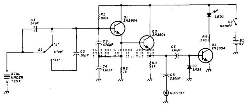
This circuit utilizes a Colpitts oscillator (Q1) paired with a buffer amplifier (Q2) to facilitate crystal testing. SI allows for the selection of three load conditions: series (S), 20 pF, and 32 pF. It is essential to keep the...
Warning: include(partials/cookie-banner.php): Failed to open stream: Permission denied in /var/www/html/nextgr/view-circuit.php on line 713
Warning: include(): Failed opening 'partials/cookie-banner.php' for inclusion (include_path='.:/usr/share/php') in /var/www/html/nextgr/view-circuit.php on line 713