
Simple Pulse Generator by IC 555 Timer
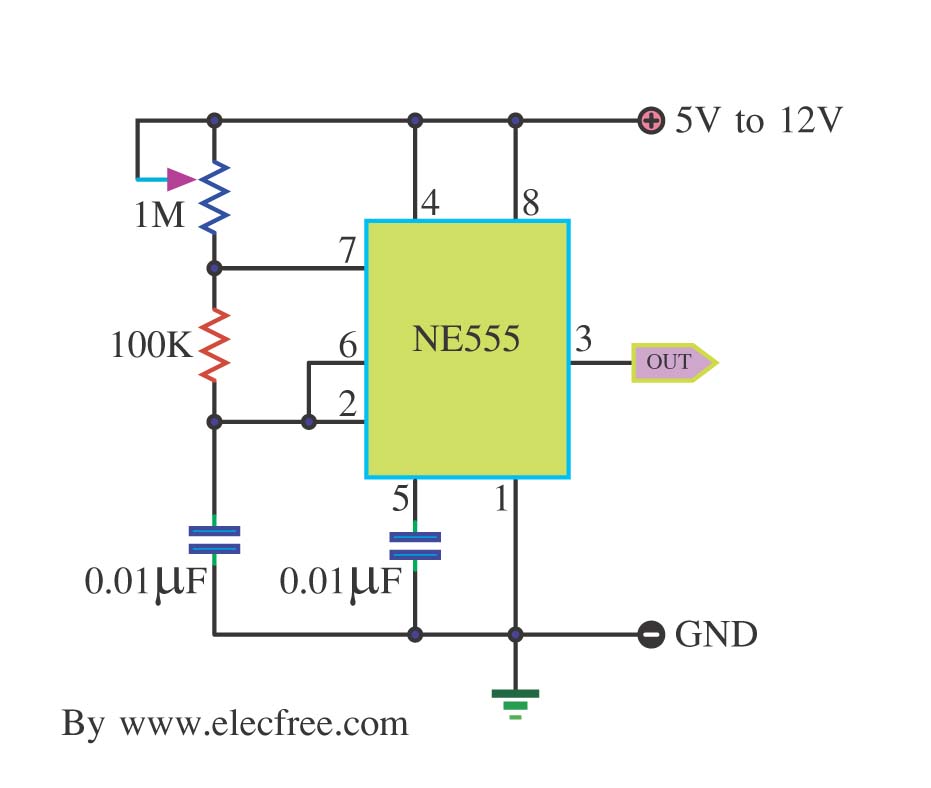
The astable oscillator circuit utilizing the NE555 timer IC serves as a versatile pulse generator, producing a continuous square wave output. This circuit is commonly employed in applications such as clock pulses, tone generation, and LED flashers. The NE555 timer operates in the astable mode, which means it continuously switches between its high and low output states without requiring any external triggering.
In this configuration, the circuit consists of the NE555 timer, two resistors (R1 and R2), and a capacitor (C1). The resistors define the charge and discharge times of the timing capacitor, ultimately determining the frequency and duty cycle of the output signal. The output frequency (f) can be calculated using the formula:
f = 1.44 / ((R1 + 2 * R2) * C1)
Where:
- R1 is the resistor connected between VCC and the discharge pin (Pin 7).
- R2 is the resistor connected between the discharge pin (Pin 7) and the threshold pin (Pin 6) as well as the trigger pin (Pin 2).
- C1 is the capacitor connected between the threshold pin (Pin 6) and ground.
The duty cycle (D) of the output signal can be calculated using the formula:
D = (R2 / (R1 + 2 * R2)) * 100%
This provides insight into the proportion of time the output signal remains high versus low.
To construct the circuit, connect the NE555 timer according to the standard astable configuration. Ensure that the power supply voltage (VCC) is within the operational range specified in the NE555 datasheet, typically between 4.5V and 15V. The output can be taken from Pin 3, which provides a square wave signal suitable for driving various loads or interfacing with other digital circuits.
In summary, the NE555 timer configured as an astable oscillator is an essential building block in electronics, capable of generating precise timing signals for a wide range of applications. Proper selection of resistor and capacitor values allows for customization of the output frequency and duty cycle to meet specific needs.This is a simple pulse generator circuit or standard astable oscillator circuit for IC 555 timer,NE555N IC. Use for.. 🔗 External reference
Related Circuits
The frequency formula of a 555 oscillator is well-known. For given resistors and capacitors, the frequency can be calculated using a specific formula derived from mathematical principles. The 555 timer IC is widely used in various applications, including oscillators, timers,...
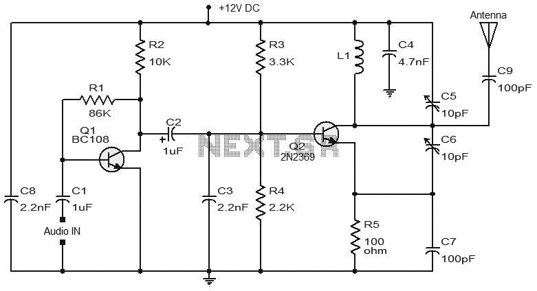
Numerous FM transmitter circuits have been published, and this is another example of a simple two-transistor FM transmitter. The first stage of the circuit is a preamplifier based on transistor Q1. This stage operates as a collector-to-base biased amplifier,...
The receiver circuit in Figure 1 activates an audio alarm when the transmitter (Figure 2) moves beyond a specified perimeter. The transmitter functions as a voltage-controlled oscillator, operating at approximately 915 MHz within the unlicensed ISM (industrial/scientific/medical) band. It...
This is a very basic circuit for flashing one or more LEDs and also to alternately flash one or more LEDs. It uses a 555 timer setup as an astable multivibrator with a variable frequency. With the preset at...

When a remote control fails to operate, the issue is often fundamental: the device does not emit light. Possible causes include dry solder joints, faulty LEDs, or a depleted battery, potentially due to a stuck button. The human eye...
The purpose of this circuit is to power a lamp or other apparatus for a specified duration (30 minutes in this case) and then turn it off. It is particularly useful for reading in bed at night, as it...
Warning: include(partials/cookie-banner.php): Failed to open stream: Permission denied in /var/www/html/nextgr/view-circuit.php on line 713
Warning: include(): Failed opening 'partials/cookie-banner.php' for inclusion (include_path='.:/usr/share/php') in /var/www/html/nextgr/view-circuit.php on line 713