
Precision Crystal Frequency Checker

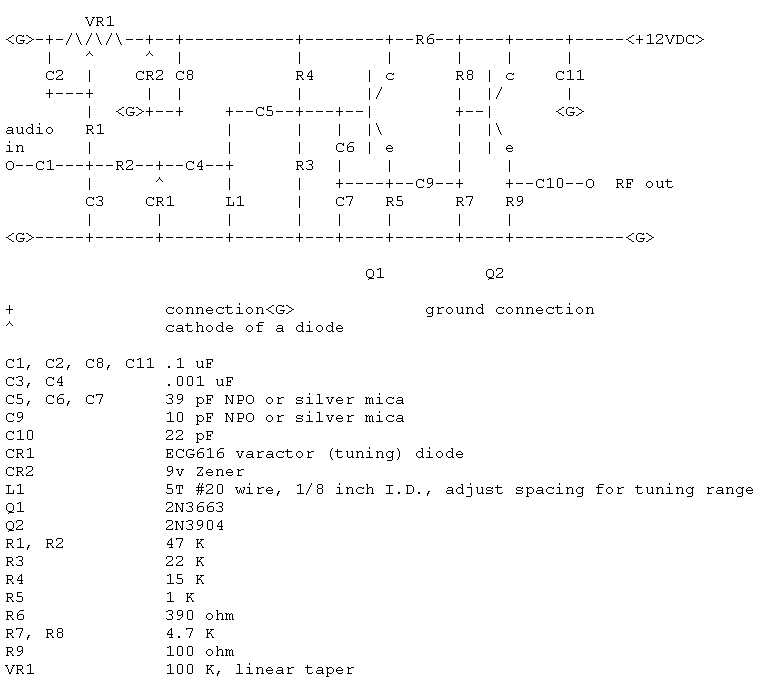
The circuit is built around a Colpitts oscillator, which is known for its ability to generate stable oscillations. The oscillator circuit consists of a transistor (Q1) configured with a feedback network that typically includes two capacitors and an inductor. The feedback network determines the oscillation frequency, which can be finely tuned to match the resonant frequency of the crystal under test.
The buffer amplifier (Q2) serves to isolate the oscillator from the load, ensuring that the performance of the oscillator is not adversely affected by the loading effects of the crystal or the measurement equipment. This configuration is particularly advantageous when testing crystals, as it allows the oscillator to maintain a consistent output while providing sufficient drive to the crystal.
The circuit features a switch (SI) that enables the user to select between three different load conditions: a series configuration (S) and two capacitive loads of 20 pF and 32 pF. These load conditions are critical for accurately assessing the characteristics of the crystal, as they simulate different operational environments in which the crystal may be used.
To achieve optimal performance, it is important to minimize lead lengths between the switch, the crystal, and the oscillator to reduce parasitic capacitance and inductance that could distort the frequency response. The design is intended to operate effectively across a frequency range of 2 to 20 MHz, making it suitable for testing a variety of crystal types commonly used in electronic applications.
In summary, this circuit provides a versatile and efficient means of testing crystals, leveraging the properties of a Colpitts oscillator and a buffer amplifier to deliver reliable performance across a specified frequency range with adjustable load conditions. This circuit uses a Colpitts oscillator (Ql) with a buffer amplifier (Q2) to test crystals. SI selects three load conditions—series (S), 20 pF, and 32 pF. Leads to SI and the crystal should be kept short. The circuit should be useful over 2-to 20-MHz.
Related Circuits
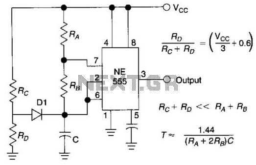
Using Rl, R7, and D1 to preset CI to one third of the supply voltage. This circuit avoids a longer first cycle period than subsequent cycles. The circuit described involves the use of resistors Rl and R7 along with diode...
The world is full of xtal oscillators twiddled by digital designers lacking in the analog design knowledge necessary. Just look at all the PC real time clocks that lags or leads by several minutes per day. And they eat...
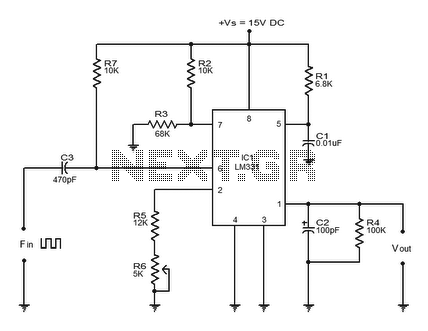
The LM331 is a precision voltage-to-frequency converter developed by National Semiconductors. This integrated circuit (IC) has various applications, including analog-to-digital conversion, long-term integration, voltage-to-frequency conversion, and frequency-to-voltage conversion. Its wide dynamic range and excellent linearity make it suitable for...
A brief note explaining the process of substituting crystal and ceramic resonator clock circuits with silicon oscillators, while emphasizing the technical benefits these devices provide in microcontroller clock applications. Silicon oscillators serve as an effective alternative to traditional crystal and...
Frequency measurement is crucial in radio construction, as it allows for the setting of desired frequencies in both receivers and transmitters, as well as monitoring frequency drifts. A frequency counter can verify oscillator functionality and ensure stability in generation....
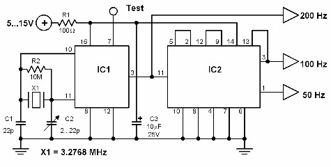
This circuit generates a 50 Hz timebase signal that is independent of the power line frequency. It is designed to provide the 50 Hz signal for electronic circuits that operate specifically with this clock frequency, primarily for circuits and...