
1KHz Sinewave Generator

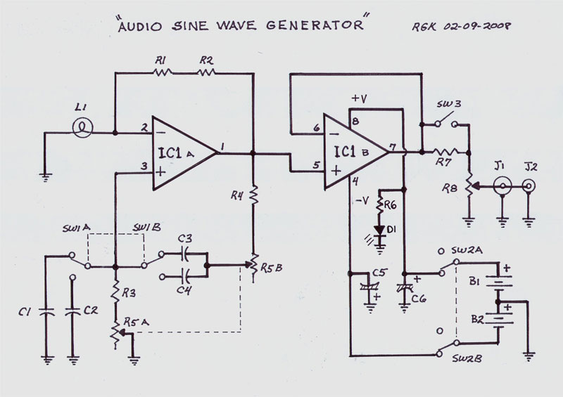
The circuit employs an inverted Wien bridge oscillator, which is renowned for its ability to generate low-distortion sine waves. The use of capacitors C1 and C2, along with resistors R3 and R4, forms the essential feedback network that determines the frequency of oscillation. The frequency of 1 kHz is achieved through careful selection of these component values, ensuring that the reactance of the capacitors and the resistance of the resistors are balanced to produce the desired sine wave output.
The variable output feature of the circuit is facilitated by adjusting R5, which directly influences the gain of the oscillator. The ability to manipulate the gain allows for a wide range of output amplitudes, making the circuit versatile for various applications. The low distortion characteristic is critical for audio applications, as it ensures that the generated sine wave closely resembles a pure sine wave, which is essential for accurate testing and measurement.
The inclusion of a small filament lamp serves a dual purpose. Primarily, it acts as a stabilizing element in the circuit, providing feedback that helps maintain a consistent output amplitude over time. The lamp's resistance changes with temperature, which aids in automatically adjusting the gain of the oscillator to counteract variations in output amplitude, thus enhancing stability.
For practical testing, the circuit is designed to interface seamlessly with audio measurement equipment. By setting R5 to achieve a reading of 1V RMS on an audio millivoltmeter, users can directly assess the output level. Additionally, with R7 adjusted fully clockwise, the output can be visualized on an oscilloscope, showing a sine wave with a peak-to-peak voltage of 2.828V. This capability makes the circuit an invaluable tool for engineers and technicians involved in audio testing and development, ensuring reliable performance in various audio applications.This circuit generates a good 1KHz sinewave using the inverted Wien bridge configuration (C1-R3 & C2-R4). Features a variable output, low distortion and low output impedance in order to obtain good overload capability.
A small filament lamp ensures a stable long term output amplitude waveform. Useful to test the Audio Millivoltmeter, Audio Power M eter and other audio circuits published in this site. Set R5 to read 1V RMS on an Audio Millivoltmeter connected to the output with R7 fully clockwise, or to view a sinewave of 2. 828V Peak-to-Peak on the oscilloscope. 🔗 External reference
Related Circuits

This circuit allows for the superimposition of a title and/or the time and date on an incoming video signal, which is particularly useful when editing video tapes. With the advent of affordable CCD camera modules, setting up a personal...
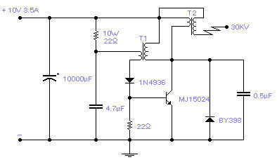
Easy to build, this high voltage generator is capable of generating up to 50KV but the breakdown voltage of the coil limits the voltage to a value somewhat lower. T2 is the ignition coil of a car and also...
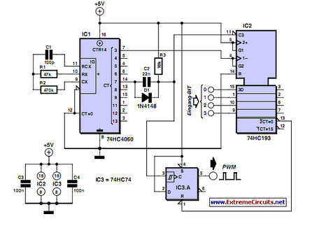
PWM waveforms are frequently utilized to regulate the speed of DC motors. The duty cycle of the digital waveform can be defined using an adjustable parameter. PWM (Pulse Width Modulation) is a technique employed to control the power delivered to...
The following circuit presents a Bell Ring Generator Electronic Circuit Diagram. Features include the generation of a dual-tone bell ringing, similar to most standard bell systems. The Bell Ring Generator circuit is designed to produce a dual-tone output that mimics...
A pulse generator typically allows control over the pulse repetition rate, pulse width, pulse delay, and pulse amplitude. More advanced pulse generators may also enable adjustments to the rise time and fall time of the pulses. The delay of...
This single integrated circuit (IC) design is based on the Wien Bridge Oscillator, generating low distortion sine waves within a frequency range of 15 Hz to 22 kHz across two output voltage levels: approximately 0-250 mV and 0-2.5 Vrms....