
Video Clock and Message Generator

The circuit design is centered around the integration of three key integrated circuits that work in unison to achieve the desired functionality of overlaying time, date, and custom text onto a video signal. The STV5730A (IC1) is the primary component responsible for the video signal processing. It takes the incoming composite video signal and utilizes its built-in capabilities to overlay text. The integration of an ASCII character generator and video timing generator within IC1 significantly simplifies the design, as it eliminates the need for additional components typically required for sync separation and timing control.
The microcontroller (IC2) serves as the central processing unit that orchestrates the operation of the system. It communicates with IC1 to determine what text to display and where to position it on the video frame. The microcontroller is programmed to handle user inputs via the onboard push buttons, allowing users to easily set the current time and date as well as the custom text message. This feature enhances the circuit's versatility for various applications.
The DS1307 (IC3) plays a crucial role in maintaining accurate time and date information. It is a real-time clock chip that operates with low power consumption and can retain its data even when not powered, thanks to the onboard lithium battery. This ensures that the time and date are preserved during power interruptions, making the system reliable for security applications where timestamps are essential.
The overall design is compact and efficient, utilizing a single power supply and standard RCA connectors for video input and output. This makes it easy to integrate into existing video systems without requiring significant modifications. The simplicity of the design, combined with the advanced features provided by the integrated circuits, allows for a cost-effective solution for anyone looking to enhance their video recording capabilities with time and date overlays.This circuit allows you to superimpose a title and/or the time and sate on an incoming video signal - very useful when editing video tapes. It`s also a good introduction to video signals and processing. The text that follows is from David`s article: With the proliferation of cheap CCD camera modules today it is now easier and cheaper than ever to set up your own video camera system.
There are an endless number of applications such as security monitoring in a shop or other area, process monitoring in a factory or laboratory, amateur CCTV transmission, or even a fancy video doorbell to name just a few. Whilst it is all very well to be able to display and record a video signal from a camera, in many cases it is also necessary to know WHEN the image was recorded, which is essential for video security and other unattended applications.
This is typically done by overlaying the time and date onto the video image itself. But how do you go about doing this, you can either purchase an expensive video switcher or VCR that has this facility built in, or you can build your own with the simple and low cost design to be described here! The following design is capable of overlaying the time and date onto any existing PAL (or optionally NTSC) composite video signal.
It is housed in a very neat and compact standard moulded casing and has standard 75ohm RCA video inputs and outputs. A single +9V to +15V DC supply is used to power the device, which can be taken from an existing camera supply if desired.
As a bonus the design is also capable of displaying a 10 character user defined text message along with the time and date. Two on board push buttons are used to set the time/date and text message, and a 3V lithium backup battery is provided on board to maintain the time and date in the absence of power.
As you can see from the accompanying photos and schematic the design is extremely simple, just three IC`s, a few passive components and not much else! For those who are familiar with video signals and the complexities involved in dealing with them then you may be wondering just HOW this design can do what it claims to with just three IC`s!.
Normally a design such as this would require sync separators, phase locked loops, horizontal and vertical timers, and that`s before you even get to generating the text on the screen!. The secret of this design lies in IC1 (STV5730A), a 28 pin surface mount on-screen display generator chip manufactured by SGS-Thomson.
This chip contains a complete system that takes incoming video and can overlay text anywhere onto the video signal. It contains an ASCII character generator ROM, video timing generator, vertical sync separator, PLL, voltage reference generators, video clamps, and more!.
Quite a lot for one chip, but such integration is required to reduce cost in today`s digital TV`s and Pay TV set top boxes which this chip is designed for. IC1 has many different modes and features that are not used in this design and consequently will not be discussed here.
All that IC1 requires to generate text onto a video image is a controller to tell it what needs to be displayed and where. IC2 is a microcontroller which tells IC1 what to display along with setup and configuration commands.
The time and date is maintained by IC3, the DS1307, a low power clock/calendar chip manufactured by Dallas Semiconductor. This chip contains a complete 12/24 hour clock and calendar that automatically maintains the time and date in the absence of power by virtue of the 3V lithium battery.
IC2 basically reads the time/date from IC3 and sends the information to IC1 to be displayed on the screen. Now lets take a look at each chip in more detail. The basic internal 🔗 External reference
Related Circuits
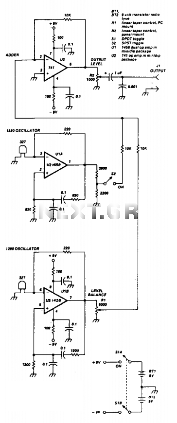
Two 741 operational amplifiers serve as the active components in this Wien bridge oscillator configuration. The dual version of the 741, known as the 1458, can also be utilized. The frequencies of the two oscillators are selected to correspond...
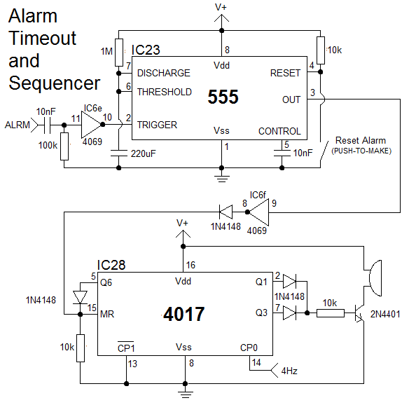
The clock is constructed using 25 CD4000 integrated circuits (ICs), three 555/556 ICs, and several discrete components. It features an alarm and a method for setting the time that is typically only seen in microcontroller designs. The complexity of...
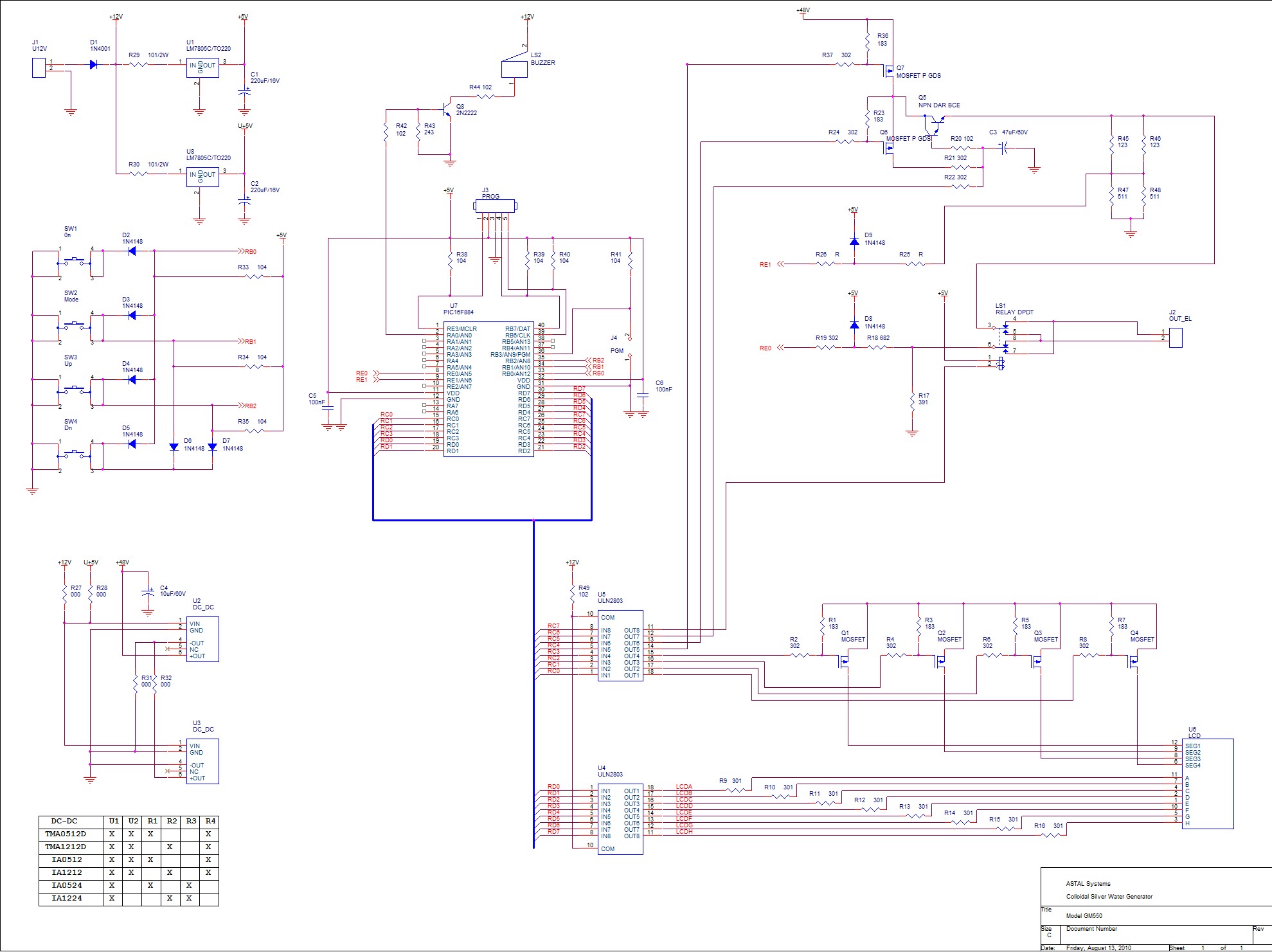
By selecting the "ON" mode, the SilverPro© initiates the process of generating colloidal solutions using the preset parameters configured by the user. The unit always recalls the last used presets. During operation, the display alternates between the total elapsed...
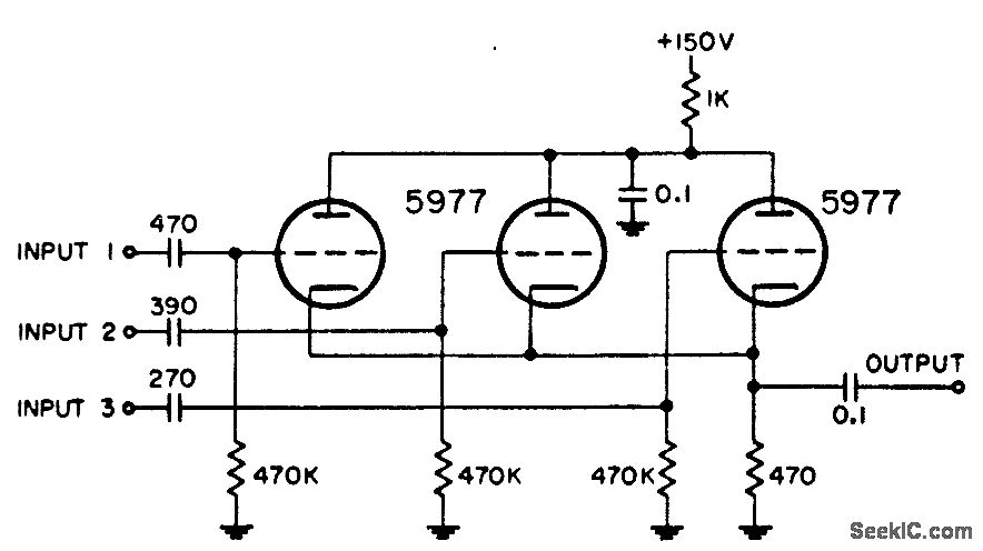
Utilized in radar systems for the integration of any three of the following components: radar video, beacon, range markers, range strobe, and azimuth markers. -NBS, "Handbook Preferred Circuits Navy Aeronautical Electronic Equipment," Vol. 1, Electron Tube Circuits, 1963, p...
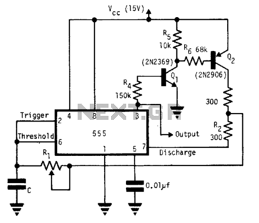
A single timing resistor ensures that the output is a square (50% duty cycle) wave at all frequency settings. Any 555 type of chip will do the job. The circuit utilizes a 555 timer IC configured in astable mode to...
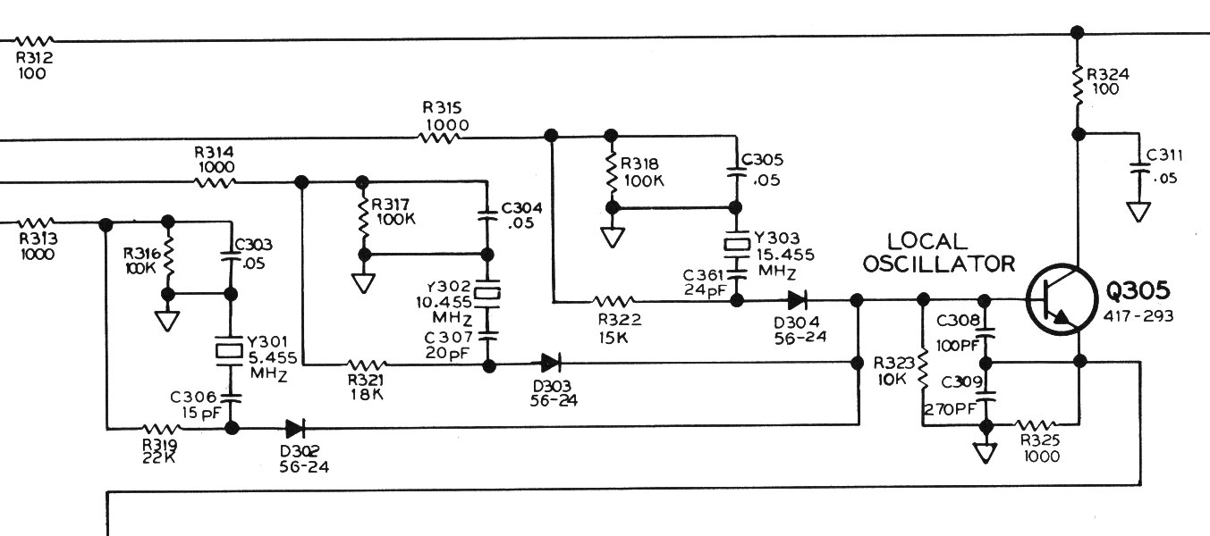
A three-channel HF receiver operates at frequencies of 5, 10, and 15 MHz, designed to receive time and frequency broadcasts from WWVH in Hawaii or the U.S., displaying time with a precision of one-tenth of a second. It features...