
1W FM Transmitter
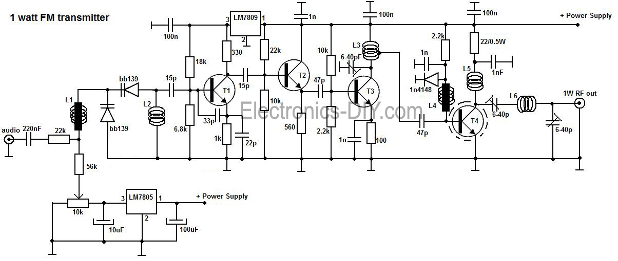
The 1-watt FM transmitter circuit is designed for efficient signal transmission with minimal distortion. The first transistor functions as a high-frequency oscillator, generating the carrier wave at the desired frequency. The stability of this oscillator is crucial for maintaining a consistent frequency output, which is achieved through careful component selection and circuit design.
Following the oscillator, the buffer stage is implemented using a second transistor. This stage isolates the oscillator from the load and ensures that any adjustments made to the transmitter do not affect the frequency stability. The buffer stage also amplifies the signal strength, preparing it for further processing.
The resonance stage is critical for tuning the transmitter to the desired frequency. It typically consists of an LC circuit (inductor-capacitor) that allows for fine-tuning of the output frequency. The quality of the components used in this stage will directly impact the transmitter's performance and range.
The final stage of the circuit employs a high-power transistor capable of delivering at least 1 watt of output power. This transistor must be adequately cooled, necessitating the use of a heatsink to dissipate heat generated during operation. Proper thermal management is essential to prevent overheating and ensure reliable performance over extended periods.
Powering the circuit requires stable voltage supplies. The LM7805 voltage regulator is employed to provide a constant 5V supply for the oscillator diodes, ensuring that they operate within their specified voltage range. The LM7809 regulator supplies 9V to the T1 oscillator stage, which is necessary for optimal operation of the transmitter.
Overall, this 1-watt FM transmitter circuit is an excellent choice for hobbyists and professionals alike, offering a balance of simplicity and performance. By following the schematic carefully and using quality components, users can achieve a reliable and stable FM transmission system suitable for various applications.A very good 1 watt fm transmitter circuit, very easy to build circuit. It has 4 transistors, one is a very stable oscillator, followed by a buffer stage to prevent frequency variation when you adjust the transmitter. Next is a resonance stage and the final stage built with a minimum 1W transistor which must have a heatsink.
You must use a LM7805 stabilizer for the oscillator diodes and one LM7809 for powering up the T1 oscillator stage. This will give you a very stable transmitter frequency 🔗 External reference
Related Circuits
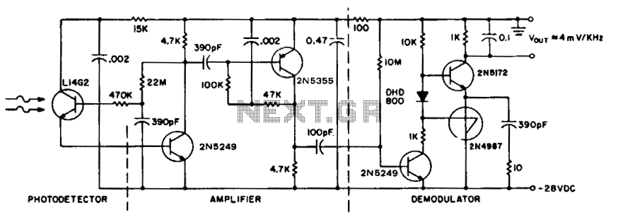
To achieve maximum range, the receiver should be constructed similarly to a radio receiver front end, as the signals received will exhibit comparable frequency components and amplitudes of the photodiode current. The primary limitation on the receiver's performance is...
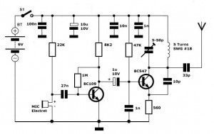
Simple FM Transmitter Circuit This simple FM transmitter circuit was built using a transistor with a transmission distance of about 300m around your home. The simple FM transmitter circuit utilizes a transistor to modulate audio signals onto a radio frequency...
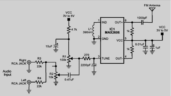
The MAX2605 and MAX2609 are compact, high-performance intermediate frequency (IF) voltage-controlled oscillators (VCOs) specifically designed for demanding portable wireless communication systems. They feature a monolithic construction with low noise and low operating power consumption, housed in a small 6-pin...

This is the BH1417 USB FM Transmitter, which features a built-in Phase-Locked Loop (PLL) circuit. It converts low-frequency audio signals into high-frequency signals, allowing any audio device equipped with an FM radio (such as stereo systems, car CD players,...
This set of two circuits forms the basis for a simple light wave transmitter. A laser beam is modulated and directed towards a receiver that demodulates the signal and presents the information, such as voice or data. The assembly...
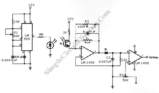
The infrared transmitter and receiver circuit depicted in the schematic diagram can function as a remote control system. The transmitter operates as an oscillator circuit, with the frequency adjustable through the R1 potentiometer (or trimmer pot). This oscillation ensures...