
1W LED Driver
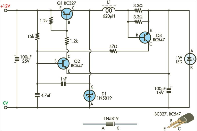
This circuit is an efficient solution for driving 1W LEDs, which require a stable current source due to their unique electrical characteristics. The design functions as a buck converter, utilizing Q1 as the primary switching transistor to regulate the output current. The inductor L1 plays a critical role in energy storage, while diode D1 ensures current flows in the correct direction to the output capacitor, smoothing the output voltage.
The oscillator formed by Q2 and its base circuit is essential for controlling the switching frequency of Q1. The inclusion of a 1nF capacitor for positive feedback is a key feature that enables the oscillation process, allowing for rapid switching and efficient energy transfer. The sensing mechanism implemented through Q3 ensures that the output current remains at the desired level of 350mA. As the output current increases, the voltage across the base-emitter resistors of Q3 rises, leading to its activation and the subsequent shutdown of Q2, thereby regulating the current flowing through Q1.
The hysteresis introduced by the resistor-capacitor combination connected to Q2's base enhances the stability of the current regulation, preventing rapid oscillations and ensuring a smooth output. The use of a salvaged toroidal inductor demonstrates an efficient approach to component selection, optimizing the circuit's performance.
Prior to connecting the 1W LED, it is crucial to adjust the output current. This can be achieved by temporarily connecting a 10Ω 5W load resistor and fine-tuning the base-emitter resistors of Q3 to attain the specified voltage across the load, ensuring safe operation of the LED once connected. This meticulous attention to detail in the circuit design and setup process is vital for optimal performance and longevity of the LEDs.This circuit is designed to drive the 1W LEDs that are now commonly available. Their non-linear voltage to current relationship and variation in forward voltage with temperature necessitates the use of a 350mA, constant-current power source as provided by this supply. In many respects, the circuit operates like a conventional step-down (buck) swit ching regulator. Transistor Q1 is the switching element, while inductor L1, diode D1 and the 100mF capacitor at the output form the energy transfer and storage elements. The pass transistor (Q1) is switch-ed by Q2, which together with the components in its base circuit, forms a simple oscillator.
A 1nF capacitor provides the positive feedback necessary for oscillation. The output current is sensed by transistor Q3 and the two parallelled resistors in its base-emitter circuit. When the current reaches about 350mA, the voltage drop across the resistors exceeds the base-emitter forward voltage of transistor Q3 (about 0.
6V), switching it on. Q3`s collector then pulls Q2`s base towards ground, switching it off, which in turn switches off the main pass transistor (Q1). The time constant of the 15kW resistor and 4. 7nF capacitor connected to Q2`s base adds hysteresis to the loop, thus ensuring regulation of the set output current.
The inductor was made from a small toroid salvaged from an old computer power supply and rewound with 75 turns of 0. 25mm enamelled copper wire, giving an inductance of about 620mH. The output current level should be trimmed before connecting your 1W LED. To do this, wire a 10W 5W resistor across the output as a load and adjust the value of one or both of the resistors in the base-emitter circuit of Q3 to get 3.
5V (maximum) across the load resistor. 🔗 External reference
Related Circuits
The object of Quick Draw is to test your reaction time against your opponent's. A third person acts as a referee and begins the duel by pressing S1, which lights LED1. Upon seeing LED1 go on, you try to...

A laser diode driver can be implemented using a voltage-controlled current source. This simple linear laser diode driver provides a cleaner drive current than other methods. A laser diode driver is an essential component in laser systems, responsible for supplying...
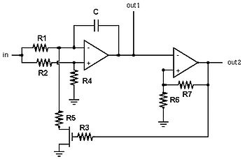
A voltage-controlled oscillator (VCO) is an electronic oscillator designed to control its oscillation frequency through a voltage input. The oscillation frequency is varied by the applied DC voltage, and modulating signals can also be introduced to the VCO for...
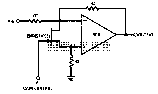
The 2N5457 functions as a voltage-variable resistor with a maximum RdS of 800 ohms. Given that the differential voltage on the LM101 is in the low millivolt range, the 2N5457 JFET exhibits linear resistance over several decades, offering excellent...
In the project LED Touch Sensing by Jeff Han, a remarkable phenomenon occurs with an LED matrix that not only illuminates but also detects finger touches. Initially, it was assumed that a special type of LED matrix was utilized,...
This circuit consists of a 6 Zone Alarm system with an LED display. The alarm system features 6 independent zones and includes a 7-segment LED display, along with one timed entry/exit zone. The 6 Zone Alarm system is designed to...