
LED As Photodiode

The LED Touch Sensing project employs an LED matrix capable of dual functionality: acting as a light source and a touch sensor. The core principle involves the capability of standard LEDs to operate in various modes depending on the biasing conditions. In this context, the LED is utilized in a reverse-bias configuration to enable its photodetection capabilities. This is achieved by ensuring that the LED operates in quadrant #4 or quadrant #3 of the I-V curve, where it can detect incident light without forward biasing.
The project incorporates a microcontroller, which is programmed to read analog values from the LED matrix. The configuration of the microcontroller's ports is critical, with TRISA set as input and TRISB configured for output. The use of analog-to-digital conversion (ADC) allows the microcontroller to interpret the light levels detected by the LEDs. When the sensed value falls below a predetermined threshold, the microcontroller activates an LED on port B.7, providing visual feedback.
The LED matrix is arranged in a grid format, allowing for row-column scanning. The code iterates through each column and row to sample the light intensity, storing the results in an array for processing. The implementation of a delay between sensing and lighting is noted, which may be attributed to the inherent response time of the LEDs and the microcontroller's processing speed.
Challenges encountered during testing include the limited sensitivity of the LEDs and potential interference from the covering shell, which can obstruct light detection. The results observed, with a detection range of only 0 to 3, suggest that further optimization may be necessary to enhance performance. This may involve experimenting with different LED types, adjusting the configuration of the matrix, or refining the software algorithms to improve the responsiveness and accuracy of the touch sensing capabilities.
Overall, the LED Touch Sensing project exemplifies innovative use of standard electronic components to create an interactive sensing interface, leveraging the dual functionality of LEDs in both emitting and detecting light.In the project LED Touch Sensing by Jeff Han, I saw a magic happen on a LED matrix. That LED matrix not only lighted but also sensed the touch of fingers. At first, I thought there should be some secret behind and the LED matrix he used must be a special one. After discussing and simple trial with Tom Igoe, I found that any LED could be used as photdiode! Actually, the LED, as its name (Light Emitting Diode) implies, is electrically a diode and can be used as a detection device similar to a photodiode. But there are some restrictions: LEDs will only detect light of wavelength shorter than the wavelength of light that the LED would emit if it was put in a circuit that forward biased the LED.
To use the LED as an optical detector, do not forward bias the LED into quadrant # 1 of the current-voltage (I-V). (Quadrant 1 is when the operating voltage and current are both positive. ) Allow the LED to operate in the solar cell mode, quadrant #4 (operating voltage is positive, current is negative), or in the photodiode mode quadrant #3 (operating voltage is positive, current is negative - ).
I am also working on touch panel simultaneously as an input device for my project daPass. However, I prefer to use LED which can be both input and output device for my project if I can conquer hopefully. The test is doing when I cover the poarta. 0 LED dark enough (seria data value <= 2), tehn the LED on portb. 7 will be triggered to light up. Porta. 0 LED is reversed by its pins to get negative voltage. Below is my code: DEFINE OSC 4 TRISA = %11111111 ADCON1 = %10000010 tx var portc. 6 rx var portc. 7 n9600 con 16468 adcVar var word main adcin 0, adcVar serout2 tx, n9600, [DEC adcVar, 13] if adcVar<=2 then high portb. 7 else low portb. 7 endif pause 100 goto main In this step, I used 2x2 LED matrix as photodiodes matrix with row-column-scanning.
But it didnt work very well. The Leds didn`t work separately. Only when did I cover all 4 LEDs that serial numbers started declining from 3. In video1 (200k, mpg), it shows how the relationship is between LED-matrix and portb. 7 LED. Portb. 7 LED lights up when I use coverlet on LED matrix. Video2 (250k, mpg) shows that how serial changes accomanpying with covering the LEDs. DEFINE OSC 4 TRISA = %11111111 TrisB = %00000000 TRISC = %10000000 TRISD = %00000000 ADCON1 = %10000010 rows var byte cols var byte bArray var portb dArray var portd tx var portc. 6 rx var portc. 7 n9600 con 16468 adcVar VAR byte main `LEDs are sensing for cols = 0 to 1 bArray. 0[cols] = 1 portd=%11111111 for rows = 0 to 1 dArray. 0[rows] = 0 pause 10 adcin rows, adcVar[rows] serout2 tx, n9600, ["adcVar[", DEC cols, 44, DEC rows, "]= ", DEC adcVar[rows], 10, 13] if adcVar <=2 then high portb.
7 pause 100 low portb. 7 endif dArray. 0[rows] = 1 next `bArray. 0[cols] = 0 next goto main I got numbers of range only 0 - 3, much less beautiful than what Tom Igoe had (which was around 20 - 300). Did I miss or mistake anything I also tried claen-lens green LEDs but still got the same result. Why is there a little bit delay between sensing and lighting Also, the LED is not sensitive so that I think there will be more trouble when I use LED dot matrix.
The cover shell will interfere with the sensing substantially. 🔗 External reference
Related Circuits
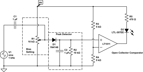
Control an LED with an audio signal; however, the output signal is only 150 mV peak-to-peak (with a 150 mV positive offset). It is understood that a higher voltage than 0.6 V is required to activate the transistor, leading...
This circuit is designed to drive a total of 42 LEDs, assuming a forward voltage of approximately 2.2V per LED and a forward current of around 21mA for adequate brightness. If the specifications of the LEDs differ significantly, modifications...
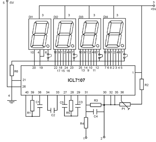
This is an easy-to-build yet highly accurate digital voltmeter designed as a panel meter. It can be utilized in DC power supplies or any application requiring precise voltage readings. The circuit uses the CL7107 Analog to Digital Converter (ADC)...

The function is designed to automatically control the speed of a fan based on the temperature. Components include a BT136 Triac, capacitor, resistor, relay, and fan motor. The circuit employs a temperature sensing mechanism to monitor ambient temperature levels. A...
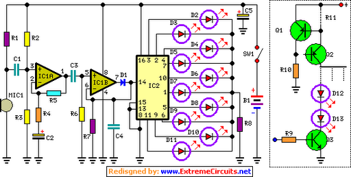
The basic circuit illuminates up to ten LEDs in sequence, following the rhythm of music or speech picked up by a small microphone. The expanded version can drive up to ten strips, each formed by up to five LEDs,...
This is a 220V LED flasher circuit designed as a reliable alternative to thermally-activated switches for flashing Christmas tree lamps. The circuit is cost-effective and easy to assemble. Schematic diagram: Component Parts: R1 10Ω. The 220V LED flasher circuit operates...