
1W PLL FM transmitter schematic
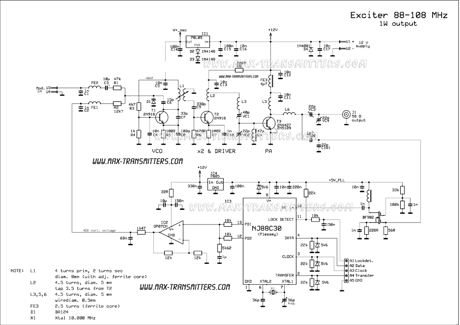
The FM transmitter circuit typically consists of several key components including an oscillator, modulator, and power amplifier. The oscillator generates a carrier frequency, which is modulated by the audio signal input. The modulation process involves varying the frequency of the carrier wave in accordance with the amplitude of the audio signal, allowing the audio information to be transmitted over radio frequencies.
In this specific design, the RF section is likely based on a low-power FM (LPFM) transmitter configuration. The use of a PLL (Phase-Locked Loop) is essential for stabilizing the frequency of the transmitter, ensuring that it operates within the designated frequency band. The PLL can lock onto a reference frequency and maintain a constant output frequency, which is crucial for reducing interference and improving signal quality.
To connect the LPFM transmitter to a PC or microcontroller, a serial data link must be established. This can involve using UART (Universal Asynchronous Receiver-Transmitter) or SPI (Serial Peripheral Interface) protocols, depending on the specific requirements of the project. The data link allows for the transmission of control signals to the PLL, enabling fine-tuning of the transmitter's frequency and other parameters.
For those interested in further exploring the capabilities of this FM transmitter, the manufacturer's website provides comprehensive documentation regarding the PLL and its implementation. This resource can assist in understanding the technical specifications and operational guidelines necessary for effectively utilizing the transmitter in various applications.Cool little FM transmitter. Suitable for study purposes, you can use the RF part of this transmitter easily for your projects. However, unless you know how to build a serial data link and connect this LPFM transmitter to a PC or a microcontroller, you won`t be able to use the PLL. All info about the PLL is available at Plessey`s web page. 🔗 External reference
Related Circuits
This one-valve (ECL82) CW Transmitter occupies a very special place in my amateur radio history. I was first licensed in 1994 but did not operate on air. I committed to only ever operate equipment which I had made myself....
The Dynaco Mark III is the highest power amplifier that was widely sold under the Dynaco name. There was a higher power amp (the Mark VI), but it wasn't widely available. The Dyna MKIII has a basic design flaw...
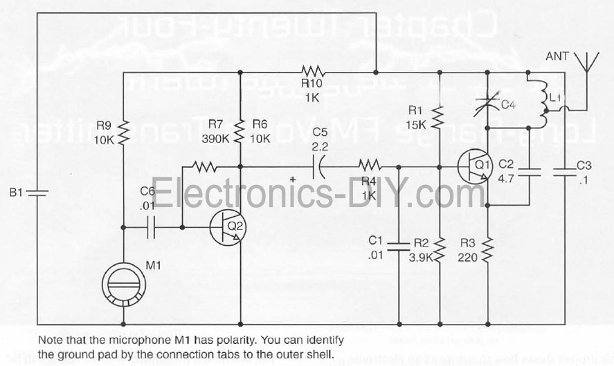
This document presents a Long Range FM Transmitter circuit, which is a highly sensitive, low-power FM transmitter. It includes a radio frequency (RF) oscillator section connected to a high-sensitivity, wide pass-band audio amplifier and a capacitance microphone equipped with...
The working voltage of capacitors C1 and C2 should be increased to 25V if a 12V power source is used. A general guideline is that the operating voltage of capacitors should be at least double the supplied voltage; for...
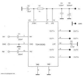
This is a 22-watt car stereo audio amplifier. The circuit is based on a single IC TDA1553 with a few peripheral components. This IC is designed for car audio applications. The TDA1553CQ integrates two 22-watt amplifiers with differential input...
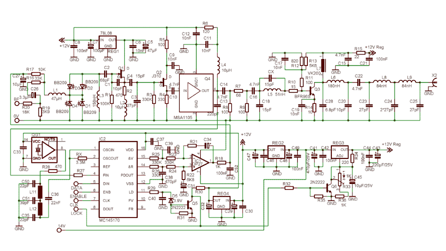
In order to simplify the transmitter design, we've used the new pll circuit from Motorola: the MC145170. This PLL includes the prescaler and a serial standard bus called SPI. We advise to use the P2 version that fixes some...
Warning: include(partials/cookie-banner.php): Failed to open stream: Permission denied in /var/www/html/nextgr/view-circuit.php on line 713
Warning: include(): Failed opening 'partials/cookie-banner.php' for inclusion (include_path='.:/usr/share/php') in /var/www/html/nextgr/view-circuit.php on line 713