
Schematics Touch Activated Alarm
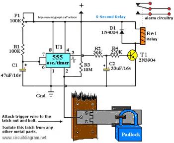
The circuit description outlines a touch-sensitive relay activation system utilizing a 555 timer IC. The primary function of this circuit is to deter unauthorized access to security cameras in computer labs by requiring physical contact to activate the relay. The design incorporates capacitors C1 and C2, which must be rated for higher voltages than the supplied voltage to ensure reliability and safety. The use of a 12V DC power supply is standard, and the relay should be selected based on the load it will control and the physical space available for installation.
The 555 timer operates in monostable mode, where pin 2 acts as the trigger input. When a person touches the designated area, the body resistance completes the circuit, momentarily pulling pin 2 low, which activates the timer. The output from pin 3 will then energize the relay, allowing it to control the connected load. The inclusion of a RESET switch provides a manual means to deactivate the relay if necessary, enhancing the functionality of the circuit.
To optimize performance, attention should be paid to the cleanliness of the contact point, as poor contact can lead to unreliable operation. The optional capacitor connected to pin 5 serves as a noise filter, which can be beneficial in environments with electrical interference. The built-in delay feature is crucial for preventing accidental relay activation, adding a layer of security against unintentional triggering.
Overall, this circuit combines simple components to create an effective security measure, demonstrating practical applications of basic electronic principles in real-world scenarios.C1/C2`s working voltage ought to be elevated to 25V in the event you decide to go with a 12V power source. Rule of thumb: the operating voltage of capacitors are at least double the supplied voltage, in other words, if the power source is 9 Volt, your capacitor(s) is a minimum of 18V.
Transistor T1 could be any approximate substitute. * Use any a ppropriate relay for the project and if you`re not tight on area, use any size. I`ve build this specific circuit to prevent students from fiddling using the security cameras in pc labs at the University I`m employed. I made sure the metal casing was not grounded. But as being the schematic shows you are able to essentially hook it as much as any type of metal surface.
I utilized a 12-vdc power supply. Use any suitable relay to deal with your specifications. A `RESET` switch (Normally Closed) can be added between the constructive and also the `arrow-with-the-+`. The trigger (touch) wire is connected to pin 2 of the 555 and will trigger the relay, using the body resistance, when touched.
It is apparent that the `touching` component has to be clean and can make good contact using the trigger wire. This particular circuit might not be suitable for all applications. Just in case you wonder why pin 5 is not listed within the schematic diagram ; it is not really required.
In particular noisy circumstances a little ceramic capacitor is placed between pin 5 and ground. It will no harm to put one or leave it out. Additional note: For those of you who didn`t discover, there`s an approximate 5-second delay build-in before activation of the relay to avoid false triggering, or perhaps a `would-be` thief, and so on. 🔗 External reference
Related Circuits
The 900 Hz tone is generated using an LC oscillator. The inductive component, "L," is provided by the inductance of the oscillator's output coupling transformer T1. This configuration is a variation of one of the two standard Hartley oscillator...
This circuit is continuously connected to a mains socket and is designed to trickle charge nickel-cadmium (Ni-Cd) batteries. In the event of a power outage, the lamp automatically turns on. Alternatively, an alarm sounder can be selected instead of...
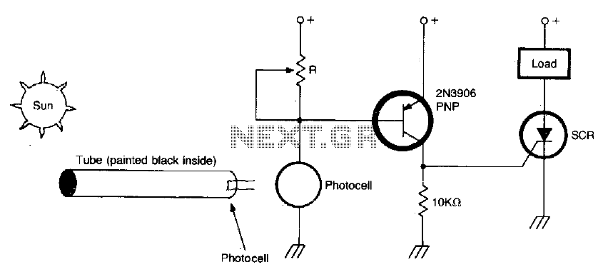
The circuit activates when light, specifically sunlight, strikes the photocell. A potentiometer, labeled R, adjusts the light level at which the alarm is triggered. Additionally, a painted tube, with a black interior, can be utilized on the photocell to...
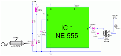
This circuit is designed around a 555 timer and utilizes very few components. Its simplicity allows even novices to construct and use it as a control device. A laser pointer, widely available in the market, can be employed to...
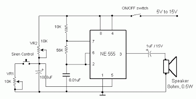
The frequency is controlled by pin 5 of the integrated circuit (IC). When the power supply is activated, the capacitor charges gradually, which alters the voltage at pin 5 of the IC, causing the frequency to increase incrementally. Once...
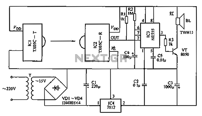
A new type of infrared system utilizes the TX05C radio sensor module for a burglar alarm designed for doors and windows. This system operates in the infrared spectrum, which is invisible to the human eye, making it suitable for...