
2 Channels RF remote control
I don`t care about the receiver`s power supply, because receiver must be working all the time. The transmitter is constituted by AT90S2323 microcontroller and TLP434 RF transmitter module at 418MHz. I have designe the transmitter for more battery economy and safe transmition of the data. o The battery economy is made it by the use of powerdown mode of AVR. In this case the AVR goes to sleep with less than 1uA (microampere) current and wait for external interrupt on pin PB1 to awake from sleep and continue operating.
If you press the S2 key, the logic of this pin goes to `0` (0V) and AVR awake frome the sleep mode (because PB1 is INT0) and check if pressed the S1 key. If not, the AVR take as pressed key the S2. If yes the AVR take as pressed key the S1. If you press the S1 key the logic of this pin and PB1 (through 1N4148) goes to `0` (0V). In this case the AVR take as pressed key the S1. After, calculate the checksum and transmit 4 times the same 4 byte sequence to make sure that receiver takes the data and goes to sleep mode until next interrupt on PB1.
When the INT0 pin (PB1) of AVR goes to 0V, the transmitter TLP434A is working. If you stop press the switch S1 or S2, the TLP is stop working. o The safe transmition of the data based to transmition of 4 bytes with serial form at 2400 bps (bits per seconds). 1st and 2nd byte are for recognition of valid remote control from receiver (like ID bytes), 3rd byte is command byte.
The relays status dependet by the value of this byte. Finaly, the 4th byte is the checksum of the earlier 3 bytes. This method use 4 bytes x 8 bit each = 32 bit length (without start and stop bits). That is mean 1 possibility at 4. 294. 967. 295 to receive the receiver, the same 4 bytes from some other RF device. This transmitter will work with all 2323 chips but better is AT90LS2323 with working voltage 2. 7 - 6 volts. The microcontroller that I use is AT90S2323 with working voltage 4 - 6 volts. Its worked fine with 3v lithium battery. The receiver constituted by RF receiver module RLP434A at 418MHz, the microcontroller AT90S2313 and the 2 relays with can handle any electric (or electronic) device up to 10 Amps (the contacts of my relays are 10Amp at 250Volts). The RLP434A is an RF receiver module with receipt frequency at 418MHz with ASK modulation. There are 2 outputs from this module, the digital, with levels from 0v to VCC (5 volts in our case) and the analog output.
Analog output is not used. The transmitter send 4 bytes with 2400bps 4 times and the receiver RLP-434A, collect them and move them to AT90S2313 to RxD pin, PD0. a. ) AT90S2313 use a hardware UART adjusted at 2400bps and the hardware UART is more stable, with smaller code, than software UART that I use in the transmitter.
If some serial data arrive at the middle-time of some other routine other than receive routine, for sure we will loose this bits of data. The hardware UART does not have this problem because have buffer for this (UDR register). This is what I mean that the hardware UART is "stable". The power supply of RF receiver constituted by 2 voltage regulator, LM7812 and LM7805. The first (12V) its only to power the 2 relays and the 2nd (5V) to power the AVR microcontroller and the RF receiver module.
The LED, is voltage indicator and the 4 capacitors are to flattening the voltage. Power on the receiver and press S1 key to transmitter. You will see that relay on PB0 of receiver will arm. If you press one more time the same key, the relay will dissarm. If you press S2 key from transmitter you will see that relay on PB1 of receiver will arm. If you press one more time the same key, the relay will dissarm. Each key is for 1 relay only. I choose to drive 2 relays and not only 1 because for some application like garage door 1 relay can handle the door (open-close) and the other to turn-on or off the light of the garage. 🔗 External reference
Related Circuits

The servo motor is a type of traditional motor that serves as the execution component in automated devices. Its most significant characteristic is its controllability; when a control signal is applied, the servo motor rotates, with its speed being...

The LED running light project can be easily implemented using microcontrollers, particularly the Microchip PIC microcontroller. This project utilizes the PIC16F877A microcontroller, which features a 40-pin IC configuration, with LEDs connected to port B. The LEDs twinkle in accordance...
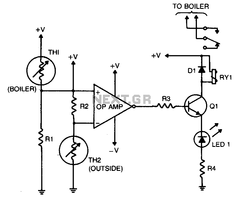
The purpose of this circuit is to control the water temperature in a hot-water heating system. It lowers the boiler temperature as the outside air temperature increases. An operational amplifier (op-amp) is utilized as a comparator. Thermistor TH2 and...
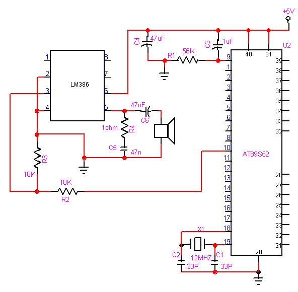
The 8051 microcontroller can play music tones. Here is a sample circuit and code that will play the music for "wishes you to be..." The 8051 microcontroller is a versatile and widely used microcontroller in embedded systems, capable of performing...
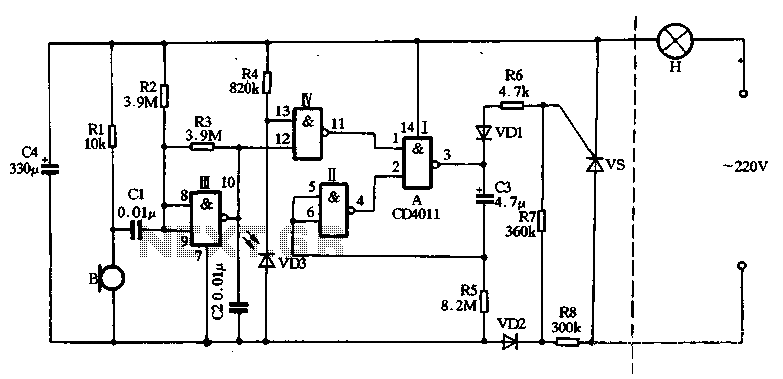
The main circuit utilizes a two-input NAND gate composed of four digital integrated circuits. This includes a NAND gate microphone amplifier circuit, a light control mechanism using an "AND gate," and a monostable delay control circuit formed by NAND...
The Intelligent Fan Controller regulates the speed of computer fans according to the internal temperature of the computer, minimizing noise levels. It utilizes a 4-wire, 2-wire, and 3-wire fan configuration in conjunction with a PIC microcontroller, specifically the PIC18F2550....