
Boiler control
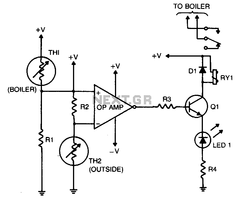
This circuit utilizes two thermistors (TH1 and TH2) to monitor temperature conditions both inside the boiler and outdoors. The thermistor TH1, located within the boiler, is responsible for measuring the internal water temperature. It is paired with resistor R1 to form a voltage divider; this configuration allows the op-amp to compare the voltage output from this divider against a reference voltage derived from the outdoor conditions.
Thermistor TH2, situated outside, works in conjunction with resistor R2 to create another voltage divider. The selection of resistor values for both R1 and R2 is crucial, as it ensures that the op-amp receives appropriate voltage levels for accurate comparison. The design is such that at 25 °F, the resistance values of TH2 and R2 are equal, establishing a baseline for the outdoor temperature reading.
The op-amp functions as a comparator, determining whether the internal temperature of the boiler (measured by TH1 and R1) exceeds the set point of 160 °F. If the internal temperature is higher than this threshold, the op-amp output will be driven high, activating transistor Q1. This transistor acts as a switch, controlling the relay RY1, which is wired to the boiler's heating element. When the relay is energized, it interrupts the power supply to the heating system, effectively turning off the boiler to prevent overheating.
This circuit design is essential for maintaining safe operating conditions within the hot-water heating system, ensuring that temperature regulation is responsive to both internal and external environmental changes. Proper selection of the thermistor and resistor values is critical for the effective operation of the system, and the use of an op-amp provides a reliable means of achieving precise temperature control.The purpose of this circuit is to control the water temperature in a hot-water heating system. What it does is to lower the boiler temperature as the outside air temperature increases. The op amp is used as a comparator. Thermistor TH2 and R2 form a voltage divider that supplies a reference voltage to the op-amp"s inverting input. Thermistor TH2 is placed outdoors, and the values of TH2 and R2 should be chosen so that when the outside temperature is 25 °F, the resistance of the thermistor and resistor are equal.
Resistor Rl and thermistor TH1 make up a voltage divider that supplies a voltage to the op amp"s noninverting input Thermistor THl is placed inside the boiler and the values of THl and Rl should be chosen so that when the boiler"s temperature is 160 °F, their resistances are equal. The output of the op amp controls Ql, which is configured as a transistor switch. When the logic output of the op amp is high, Ql is turned on, energizing relay RYl. The relay"s contacts should be wired so that the boiler"s heat supply is turned off (relay energized).
🔗 External reference
Related Circuits
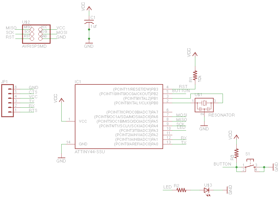
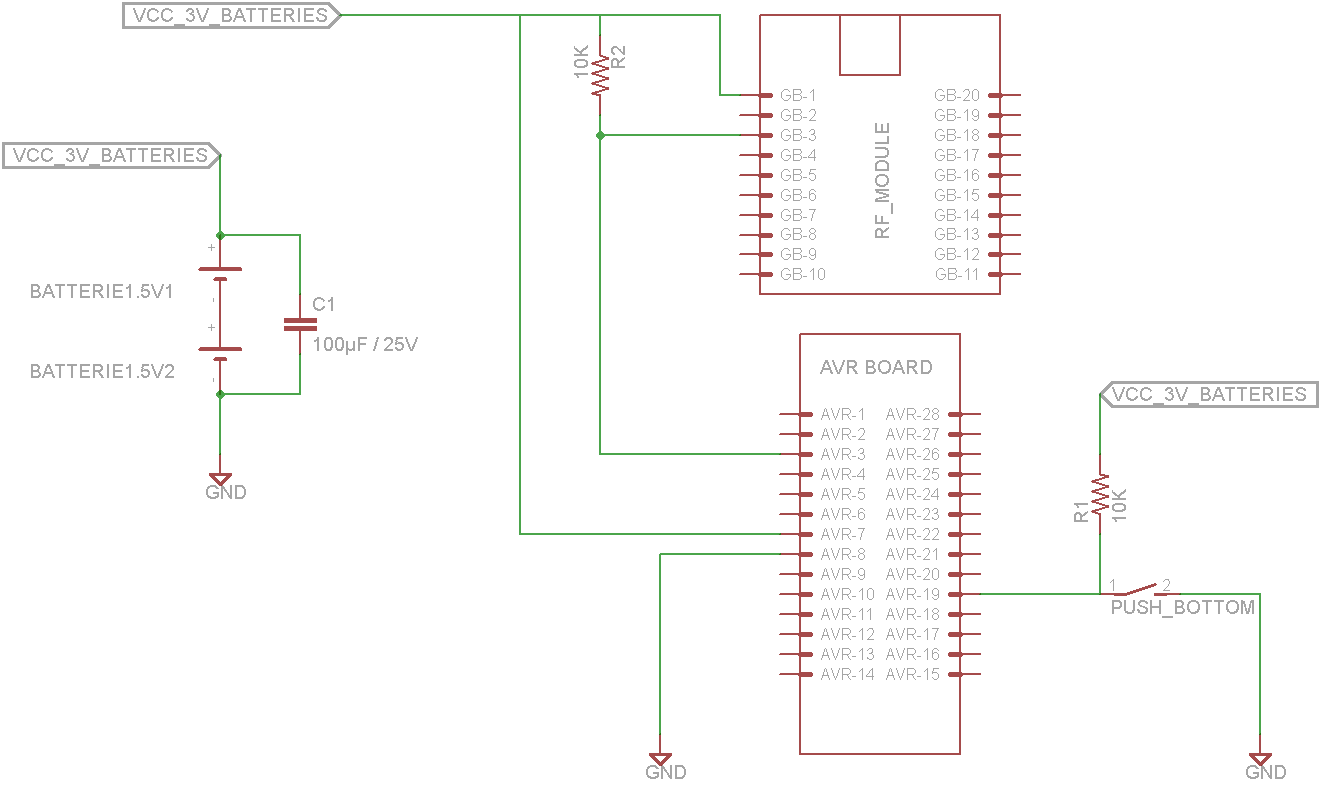
For this week's assignment, a chip design was provided, and the task was to incorporate a button and an LED (light-emitting diode). The objective was to fabricate the chip and program it to interact with the light and button....
This volume controller equalizer electronic project utilizes the LM1036 DC tone volume controller, which includes a volume and balance circuit suitable for stereo applications. The LM1036 features an additional control input that facilitates simple loudness compensation. It provides four...
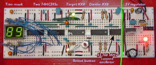
One of the nicest features of the 8-bit KX8 microcontroller (manufactured by Freescale Semiconductor) is that it includes an internal clock generator (ICG). This allows the chip to run without the trouble and expense of an external crystal or...
The circuit consists of an infrared transmitter-receiver pair that uses infrared beam transmission to switch the toy car on or off. It can be modified to allow the toy car to turn left or right. To operate the toy...
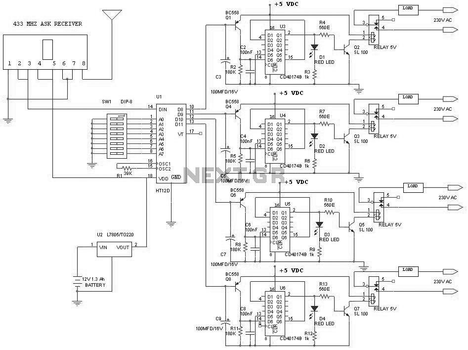
This tutorial demonstrates concepts for creating a lamp with dual actuation. The lamp can be controlled through a parallel switch or by a relay that is managed using an RF module based on the ZigBee protocol (IEEE 802.15.4). The...
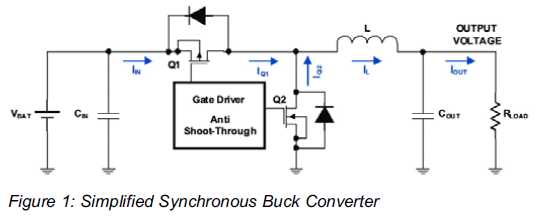
Increased Flexibility for Low-Power Synchronous Buck Converters. Contemporary synchronous buck converters designed for portable applications offer a power-save mode operation to sustain high efficiency throughout the entire range of operation. Modern low-power synchronous buck converters are essential components in portable...