
2 LED flasher with two 2N3904 transistors

The described circuit is an astable multivibrator configuration utilizing two 2N3904 NPN transistors, which are fundamental components for creating a simple LED flasher. This circuit operates continuously in a toggling manner, causing the LED to flash at a predetermined rate. The choice of transistors is flexible; other NPN transistors such as 2N4401, 2N2222, NTE123A, NTE123AP, and NTE159 can also be employed, allowing for experimentation with various transistor types available in a typical electronics toolkit.
In this configuration, the 470-ohm resistor plays a crucial role in limiting the current flowing through the LED, ensuring it operates safely at approximately 20mA. An alternate resistor value of 390 ohms can be used as a substitute, providing a slight variation in brightness. If a green or yellow LED is utilized, which typically requires a higher current, it is advisable to adjust the resistor value to 270 or 330 ohms to accommodate the increased current demand and maintain appropriate brightness levels.
The flash rate of the LED is regulated by the resistor-capacitor (RC) network formed by the 39K resistors and the 10µF capacitors. The time constant of this network dictates the duration of the 'ON' state of the LED. Notably, the two halves of the circuit—each consisting of one transistor, a resistor, and a capacitor—do not need to be identical. By varying the resistor and capacitor values on either side, unique duty cycles can be achieved, resulting in varied flashing patterns and effects.
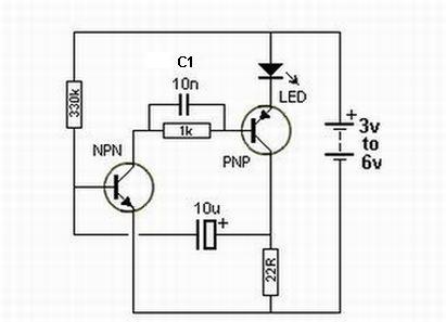
The typical flash rate for this circuit is approximately one cycle per second, but this can be adjusted by modifying the resistor and capacitor values, providing further flexibility in the design. This simple yet effective LED flasher circuit is ideal for various applications, including visual indicators, decorations, and educational demonstrations in basic electronics.This is a simple LED flasher using two 2N3904 transistors. Classic astable multivibrator using 2 transistors. Transistor is not critical. Try these: 2N4401, 2N2222, NTE123A, NTE123AP, NTE159, TUP/TUN and those in your junk box, you may find that most of them will work. Obviously, the 470 ohm resistor determines the LED's brightness and limits the current flow to about 20mA.
390 ohm can also be used as a save value. If you decide to go with a green or yellow led, which draw more current, you may want to replace the 470 ohm with 270 or 330 ohm values. Flash rate is determined by the 39K resistors and the 10µF capacitors (determines the 'ON' time). The two sides do not have to match. Different values for each side can give a nice effect for unique duty-cycles. Flashrate for above circuit is 1 cycle per second. 🔗 External reference
Related Circuits

The circuit illustrated in Figure 1 generates a precise variable-frequency sine wave intended for use as a general-purpose reference signal. It incorporates an 8th-order elliptic switched-capacitor low-pass filter (IC3), which is clocked by a 100 kHz square wave produced...
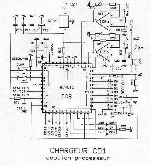
Note first the battery to be treated at the center of the figure. It is connected to contacts of a relay. The diagram shows the relay at rest. Under these conditions the battery is in SHOCK. His pole -...
Oscillation is expected at the resonant frequency where the positive feedback is in phase with the input, specifically at 0 degrees. For oscillation to take place, the gain must be equal to or greater than 1 at that frequency....
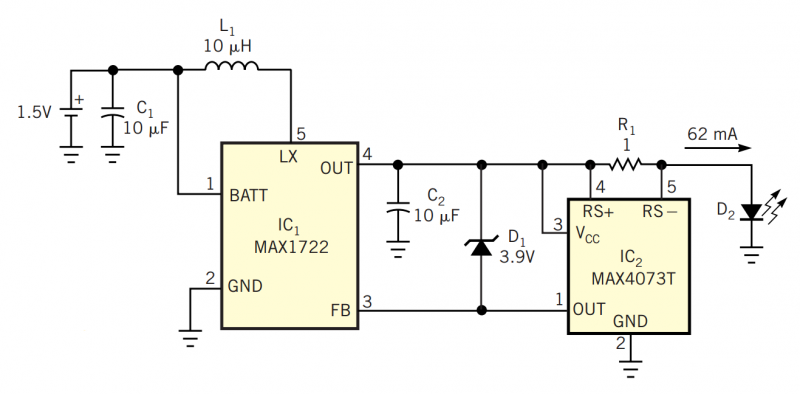
Although white LEDs are common in a variety of lighting applications, their 3 to 4V forward-voltage drop makes low-voltage applications challenging. Charge pumps and other ICs are available for driving white LEDs, but they generally don't work with the...

Most audio amplifier systems must have preamplifiers with many different characteristics. These include high-gain linear response for magnetic microphones, low-gain linear response for tuners, and high-gain RIAA equalization for magnetic phone cartridges. To meet this broad requirement, most amplifier...
A functional AM transmitter has been completed, primarily based on Phil's Li'l 7 Transmitter design. Achieving oscillation in LC-based transmitters can be challenging without the correct combination of tubes and coils. This transmitter utilizes a 6J5 and a 6SA7...