
reference design digitally controlled sine wave generator

The circuit's design emphasizes precision and flexibility in generating sine wave signals suitable for various applications. The 8th-order elliptic filter is a critical component, as its design allows for a steep roll-off characteristic that effectively suppresses unwanted harmonics, thus ensuring signal integrity. The use of a microcontroller to generate the clock signal provides programmability, enabling users to adjust the frequency output dynamically.
The voltage supervisor (IC1) plays an essential role in maintaining circuit stability, especially in environments where power fluctuations may occur. This component monitors the supply voltage and ensures that the circuit operates only when sufficient power is available, preventing potential damage or erroneous outputs.
The relationship between the clock frequency and the input frequency is crucial, as maintaining a 100:1 ratio allows for a broad range of sine wave frequencies to be generated. This flexibility is beneficial for applications requiring precise frequency control. Additionally, the provision for attenuation and DC level adjustment ensures that the output remains within safe limits, thereby preventing distortion or clipping of the waveform.
Overall, this circuit provides a robust solution for generating high-quality sine wave signals, making it an invaluable tool for testing and reference purposes in various electronic applications.The circuit of Figure 1 produces an accurate variable-frequency sine wave for use as a general-purpose reference signal. It includes an 8th-order elliptic, switched-capacitor lowpass filter (IC3) that is clocked with a 100kHz square wave generated by microcontroller IC2.
(Any other convenient squarewave source is also acceptable. ) The microcontrol ler is clocked by a 10MHz oscillator module. A voltage supervisor (IC1) ensures correct operation in the event of a power failure. IC3 sets the filter`s cutoff frequency at 1/100 the clock frequency. The 8th-order elliptic filter`s sharp rolloff sharply reduces the harmonic amplitudes in a 1kHz square-wave input, thereby producing a near-perfect 1kHz sine wave at its output. Using divider-chain logic or a processor, you can then create a digitally adjustable sine-wave source by adjusting the clock and input frequencies while maintaining a ratio of 100:1 between them.
To prevent clipping at the positive and negative peaks, attenuate the input signal and superimpose it on a dc level of VCC/2. The result (for a 5V input) is a 2. 25V peak-to-peak output. 🔗 External reference
Related Circuits
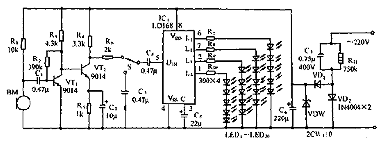
The circuit depicted in the figure involves the LD168, which functions as a sound level indicator for tape recorder speakers. It features four outputs capable of directly driving multiple light-emitting diodes. Additionally, the device can be activated by a...

Generators that do not use fuel to operate provide 24 hours of electricity for continuous use. In the early days of this invention, a significant issue arose: the battery powering the generators would deplete within 20 to 30 minutes...
This circuit utilizes the versatile MAX038 function generator. While some advanced features of this integrated circuit (IC) are disabled in this configuration, it is capable of generating sine, triangle, and square waves by adjusting the A0 and A1 pins,...
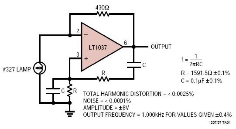
A lamp provides amplitude stability while the very low noise amplifier generates a pure sine wave signal. The resistance and capacitance values determine the oscillator frequency, while the feedback resistor regulates the lamp current and output amplitude. The circuit described...
This circuit is effective for testing audio circuits using broadband noise. It employs three inexpensive C-MOS integrated circuits (ICs) that produce a series of output pulses with randomly varying widths. The audio noise generator is designed to drive earphones...
The PCB is at the center of any electronic product. Literally, the enclosure surrounds the board, and figuratively, all the mathematics, the science, the software, these all run on the board. That’s why the PCB is at the center...