
2 Transistor Mini FM Transmitter

To achieve some tuning flexibility, a 4-40 pF trimmer capacitor (optional) can be connected in parallel with the 1 H coil, labeled L1. Capacitors C1/C4 and C5/C6 should be ceramic types, preferably NPO (low noise). Capacitors C2 and C3 can be either electrolytic or tantalum types. The antenna can be made from a piece of 12-gauge wire or a piece of piano wire ranging from 6 to 12-gauge.
To find a clear reception, set the FM radio to a quiet spot in the lower frequency range (around 88 MHz) and use a non-conductive, non-metallic trimmer tool to fine-tune the capacitor until the clearest signal is found. Some experimentation may be required. Most component values are not critical, allowing for adjustments to test different configurations. If substituting transistors with similar alternatives, it may be necessary to adjust the collector voltage of Q1 by modifying the values of resistors R2 or R3, as this will affect the bias on the base of Q1. The collector voltage should be approximately half of the power supply voltage (around 4 to 5 volts).
The recommended capacitor type is ceramic, preferably the NPO 1% (low noise) type or an equivalent. However, the choice of capacitors is not critical; any available capacitors can be used, but electrolytic or tantalum capacitors should be avoided. If the circuit is intended for outdoor use, selecting temperature-stable capacitors may be advisable. To ensure the circuit operates correctly, a signal must be present at the microphone; otherwise, it will not function. An example of a suitable sound source is an old mechanical alarm clock, which can be placed near the microphone to capture the ticking sound. Alternatively, gently tapping the microphone can help locate the signal on the receiver.
For optimal performance, attention should be paid to the layout of components and the quality of solder joints to minimize noise and interference. Proper shielding may also be beneficial to enhance transmission clarity and reduce susceptibility to external electromagnetic interference. Testing various configurations and placements will allow for fine-tuning of the transmitter's performance, ensuring reliable operation for its intended applications.This is a mini FM transmitter built and powered using 2 transistors, designed by Tony van Roon. This small transmitter is simple to build and its transmissions could be picked up on any common FM radio. It possesses a range of approximately 1/4-mile (400 meters) or even more, depending on the line-of-sight, obstructions by big buildings, and so on
. It`s excellent for room monitoring, baby listening, nature exploration, and many others. Nothing critical here. To get a bit of tuning out of the coil you could put a 4-40pF trimmer capacitor (optional) parallel over the 1 H coil, L1. C1/C4 and C5/C6 are ceramic capacitors, preferably NPO (low noise) types. C2/C3 are electrolytic or can be tantalum types. The antenna is nothing more than a piece of 12 ³ wire or a piece of piano wire from 6 ³ to 12 ³. Set your FM radio for a clear, black spot in the lower end of the band (88MHz). Then, using a non-conductive/non-metallic trimmer tool, fine-tune this capacitor to find the clearest reception.
A little bit testing and patience might be in order. Almost all of the components values aren`t crucial, so you are able to attempt adjusting them to see what occurs. In the event you determine to substitute transistors with something similar you currently have, it possibly needed alter the collector voltage of Q1 by altering the value of R2 or R3 (because you change transistors, it changes this bias on the base of Q1).
It ought to be about 1/2 the power supply voltage (about 4 or 5volts). The default for the capacitors kind is ceramic, preferably the npo 1% (low noise) kind or equivalent. But generally almost nothing vital right here. Use any capacitor you`ve laying around, but NO electrolytic or tantalum caps. Only in case you intend to use this circuit outside the house you might wish to choose much more temperature stable capacitors.
To find the signal in your receiver, make certain there`s a signal coming into the microphone, otherwise the circuit will not work. I use an old mechanical alarm clock (you realize, with these two big bells on it). I put this clock by the microphone which picks up the loud tick-tock. I am sure you get the idea Or you are able to just lightly tap the microphone whilst looking for the location with the signal in your receiver.
🔗 External reference
Related Circuits
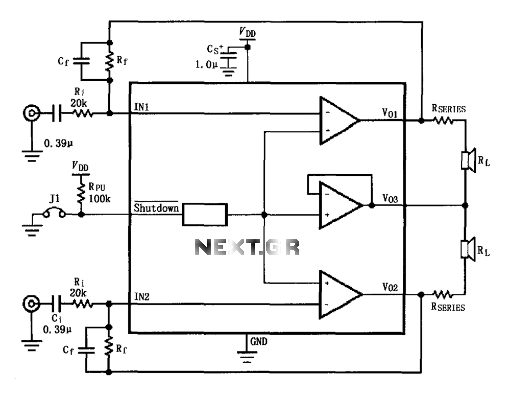
The circuit for the LM4910 is designed to minimize output noise and reduce power consumption. The output noise is attenuated by utilizing a resistor in series with the load. A feedback resistor Rf is used in conjunction with a...
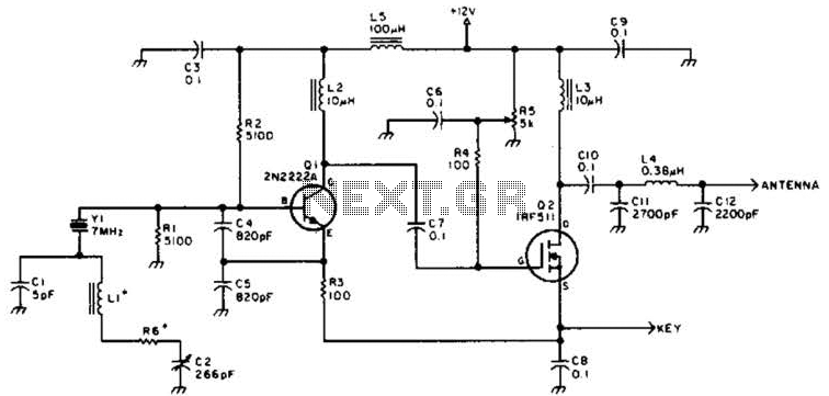
A DSB transmitter is significantly less expensive to construct compared to an SSB transmitter since it does not require filters or phasing networks. This circuit can generate an output of up to 1 watt on the 10-meter band. The...
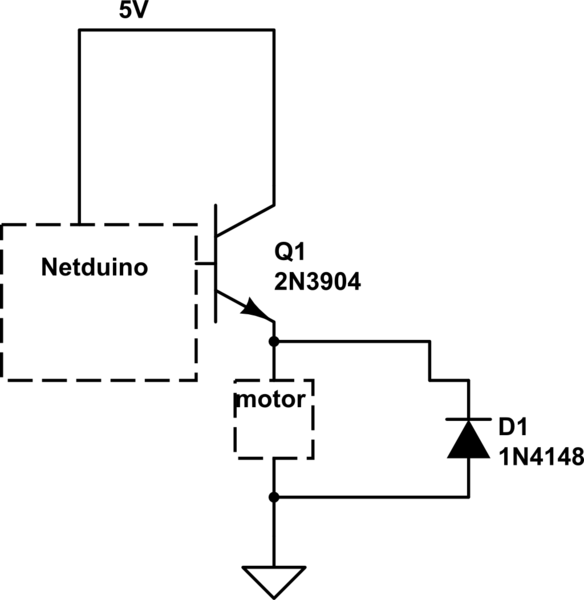
When the motor is connected in this manner, the Netduino activates the transistor, but nothing occurs. Swapping the motor with an LED results in the LED lighting up, indicating that the motor is not receiving sufficient power. Connecting the...
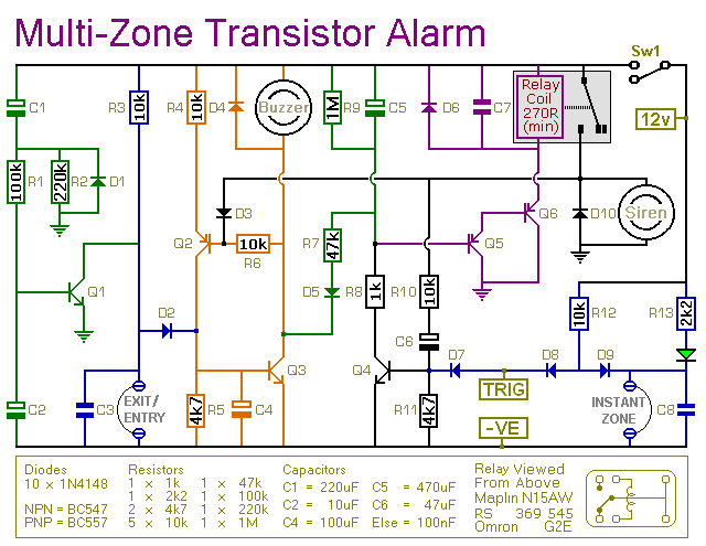
This transistor-based alarm system incorporates automatic exit and entry delays, along with a timed bell cut-off and system reset functionality. In addition to the exit/entry zone, the fundamental alarm board includes one instant zone, which is sufficient for many...

The LV2282VA is an FM Transmitter integrated circuit (IC). The multiplex (MPX) block generates a stereo modulated composite signal from left (L) and right (R) audio inputs. The radio frequency voltage-controlled oscillator (RF VCO) incorporates an FM modulation function....
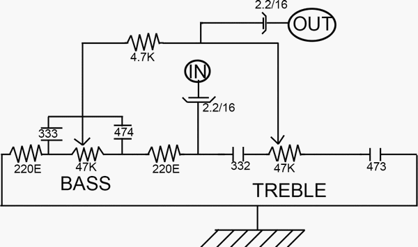
This low-cost bass treble circuit consists of capacitors, resistors, and two potentiometers for bass and treble control. The circuit can be assembled without a veroboard, as the components can be soldered directly due to the simplicity of the design....