
netduino Motor not working via transistor

The circuit described involves a Netduino microcontroller controlling a motor through a transistor. In this configuration, the Netduino's GPIO pin is connected to the base of the transistor through a resistor, which limits the base current to prevent damage to the microcontroller. The transistor acts as a switch, allowing higher current from the power supply to flow through the motor when the base is activated.
The setup requires careful consideration of the voltage levels involved. The Netduino operates at 3.3V, which may not fully saturate the transistor, especially if it is a standard bipolar junction transistor (BJT). This could lead to insufficient voltage across the motor, causing it to stall. A Darlington pair configuration was attempted, which provides higher current gain but may introduce additional voltage drop, exacerbating the issue.
The motor and a flyback diode should be connected from the collector of the transistor to the positive supply (5V). The emitter of the transistor should be grounded to complete the circuit. The resistor connected to the base is crucial; a value of 1k-ohm is common, but testing with lower values like 220 ohms can help determine if the base current is adequate.
In summary, the circuit's operation hinges on the proper selection of components and their connections. Ensuring that the transistor is correctly biased and that the motor receives sufficient voltage is essential for successful operation. If issues persist, verifying the programming of the Netduino and the integrity of the components is recommended.When the motor is connected in this fashion, the netduino activates the transistor, but nothing happens. If i swap the motor with an LED, the LED does light up, so that incidates that the motor isnt getting enough power.
So i connect the motor direct to power and gnd, and it spins. Does this mean that the transistor is drawing so much current that it is stopping the motor working Also, I don`t see why the 100ohm resistor is there - it would be better if it were connected between netduino and base of the transistor. pjc50 Apr 27 `13 at 17:29 Updated schematic. Removed unnessecary resistor, and even tried replacing the transistor with a darlinton pair, but in this case there was even less power, as a LED shows even less brightness in place of the motor.
Wayneio Apr 27 `13 at 17:48 I believe the netduino IO to be 3V3 and this means the emitter of the transistor can never be higher than about 2. 7V with any load connected. This is realistically the problem you have - the motor is only receiving about half of the 5V it needs and is therefore stalling.
The led works because it only needs a couple of volts (more than likely). You need to have the motor and diode (same way round as drawing shows) from the collector up to +5V. The emitter needs grounding and the input to the base (from the netduino) goes via a 1k resistor. Okay, that makes sense. I have swapped the motor and diode to the collector side of the transistor, but am still not seeing the motor move. Could it just be that the output from the netduino IO is not enough Wayneio Apr 27 `13 at 18:17 Have you used a 1kohm resistor in the base As a quick test if you disconnect the resistor from the IO pin and link that point up to +5V does the motor turn If yes, then maybe you haven`t programmed the IO pin correctly.
If no then try linking that point up to +3V3 - this should still turn the motor - if not then try lowering the 1kohm to 220 ohm - let me know Wayneio Andy aka Apr 27 `13 at 18:24 Yeah, 1k. I added an LED in series, after the emitter to ensure the circuit was working. The transistor`s base pin then was connected the the +5v, and the LED lit up(so bright nearly blew it) but the motor still did not turn.
I tried the motor again to just 5v and gnd and it worked, so there must be a problem with either the transistor or netduino IO Wayneio Apr 27 `13 at 18:35 You need to take out the LED because it will reduce the drive to the motor by 2V or maybe more. Try again without the LED Wayneio Andy aka Apr 27 `13 at 18:42 🔗 External reference
Related Circuits
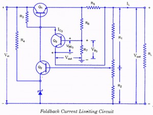
If the load resistance (RL) is reduced or the load terminals are accidentally shorted, a very large load current will flow, potentially damaging the pass transistor (Q1), diode, or other components. Fuse protection may not be sufficient, as the...
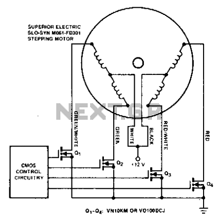
Stepping motors are commonly utilized in disk drives and machine control applications. MOSPOWER transistors serve as excellent motor drivers due to their immunity to second breakdown. It is important to note that snubbing networks are unnecessary since load line...
The individual has been engaged in garden railroading for just over a year, utilizing skills from various hobbies. They have designed and built two scratch-built bridges and nearly 100 trestle bents to support a 200-foot main line. Their interests...

This notch filter is beneficial for tunable band-reject applications in the audio range. The specified values will provide a tuning range of approximately 300 to 1500 Hz. The notch filter is designed to attenuate a specific frequency while allowing others...
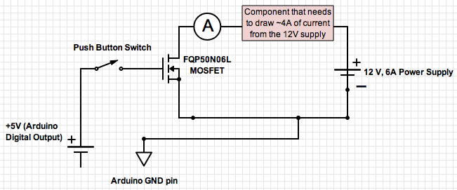
If the ground of the Arduino is disconnected from the negative terminal of the power supply, current flows through the MOSFET, even when the switch is not closed. In an electronic circuit involving an Arduino and a MOSFET, maintaining a...
The simplest of all motor controllers (besides a straight on/off switch) is the contactor controller. Aaron designed this contactor controller for use in his electric scooter project. It is based around three 12V relays, two 12V batteries, two switches...