
2 VALVE TRANSMITTER
The schematic of this transmitter circuit emphasizes a straightforward design that leverages readily available components. The Pierce oscillator design is favored for its simplicity and reliability, providing a stable frequency source for RF applications. The RF choke, designed with precise turns and wound on a ferrite core, ensures efficient RF signal handling while minimizing losses. The output tank circuit's construction on a plastic conduit allows for easy adjustments and optimizations, crucial for achieving desired performance across multiple frequency bands. The careful selection of capacitors and resistors in the circuit design aids in managing high voltages safely, while also enhancing the keying performance of the transmitter. The layout of the chassis is purposefully designed for accessibility and safety, ensuring that all high-voltage components are adequately shielded. The inclusion of a PSU connection further enhances the functionality of the device, making it a versatile tool for various RF projects. Overall, this transmitter design exemplifies a balance of simplicity, efficiency, and adaptability, suitable for both amateur radio enthusiasts and educational purposes.This transmitter is very stable and will deliver up to seven watts of power with the components and tubes shown. Do not be put-off by valves as they are VERY easy to work with and it seems that there are quite a few valves around.
Because no-one wants these obsolete things they may be bought for next to nothing at radio rally`s. If you are not too particular what type of valve you want then there are lots of valves available. Above is the circuit of the transmitter including the coil winding information. The oscillator is a simple untuned Pierce oscillator which will oscillate at the fundamental frequency of the crystal. A 25pf variable capacitor between the grid of the first valve and earth will allow the final frequency to be "pulled" a little but I never used this facility.
The RF choke in the anode of the two valves is made up of 34 turns of enamelled wire wound on a 1/2" ferrite ring (2. 2mH). The output tank circuit is wound on a piece of 2" dia plastic conduit tube. The object is to have as many turns of wire in circuit as it is possible to have on the band of interest.
The output tuning capacitor should normally be set to about 10% when selecting the tapping for any particular band. The cathode resistor and 2. 2uf capacitor give quite a nice keying envelope to the keyed output. When the key is UP (off) there is about 100 volts DC across the 2. 2uf so this component must be rated in excess of 100v. Because of the high voltage you should NOT use a CMOS keyer circuit without suitable buffering. I obtained my 2. 2uf capacitor from an old telephone because they nearly always have a 2. 2uf 250v non-electrolytic capacitor somewhere in the circuit. The chassis is built using aluminium plate, drilled as shown above. An extra hole must be added to pass the connection from the PA anode to the tuning coil. If this connection is made using the output coupling capacitor under the chassis then there will be no high DC voltages above the chassis.
The mains input terminals must be suitably protected to prevent contact with the mains input. Here is the rear panel of the transmitter. I also mounted sockets for connection to the PSU so that the finished transmitter is also a high voltage PSU for other projects. The front panel is very uncluttered having only two controls; BAND switch and TUNE. I also added two switches, one to switch on the PSU HT and the other to key the TX for tuning purposes.
The oscillator is un-tuned so the only tuning procedure required is to select the band (coil tapping) and peak it for maximum RF output. The valves used were selected because they had B7G bases and were the first I put my hand on when I reached into my junk-box.
Virtually any pentode valves will work in this application. An EL84, for example, will deliver over ten watts in this circuit but the valves quoted will deliver seven watts from 3. 5 to 30 MHz. If you should use another tube then don`t forget to check the screen voltage. If it is less than 250v then you will need a resistor in the screen supply to the valve. The output tank coil should be built as shown. I only needed 40 turns on this one but on an earlier version I used a slightly smaller diameter tube and needed 58 turns (3.
5MHz). Leave space for 65 turns (3. 5MHz) then remove turns to achieve the lowest frequency you want to use. Adjust the tappings so that you achieve full power on each band with only 10% of the tuning capacitance in circuit. The coil can be easily tapped by masking adjacent turns with tape then scraping and soldering as shown in the photograph.
If you want to add more turns to support the 1. 8MHz band then you could either use the full 100 turns or add another (smaller) coil in series with the main coil. 🔗 External reference
Related Circuits
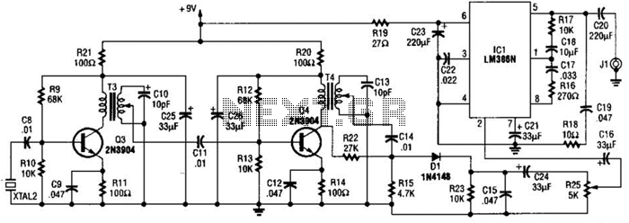
The 2.25-MHz oscillator Q1 drives amplifier Q2 and XTAL1, an ultrasonic transducer. The transducer is a lead zirconate-titanate type. Taps on T1 and T2 provide low-impedance drive points. The circuit consists of a 2.25-MHz oscillator (Q1) that serves as the...
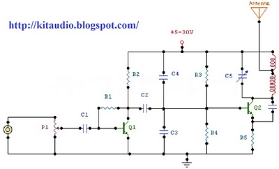
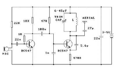
The circuit is a radio frequency (RF) oscillator functioning at approximately 100 MHz. Audio signals captured and amplified by an electret microphone are routed to an audio amplifier stage constructed around the first transistor. The output from the collector...
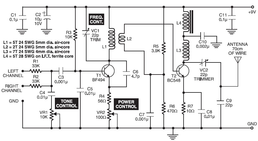
A high-quality FM transmitter circuit designed for use with amplifiers, providing a strong signal strength with a range of up to 500 meters and a power output of approximately 200 mW. This FM transmitter circuit is engineered to deliver reliable...
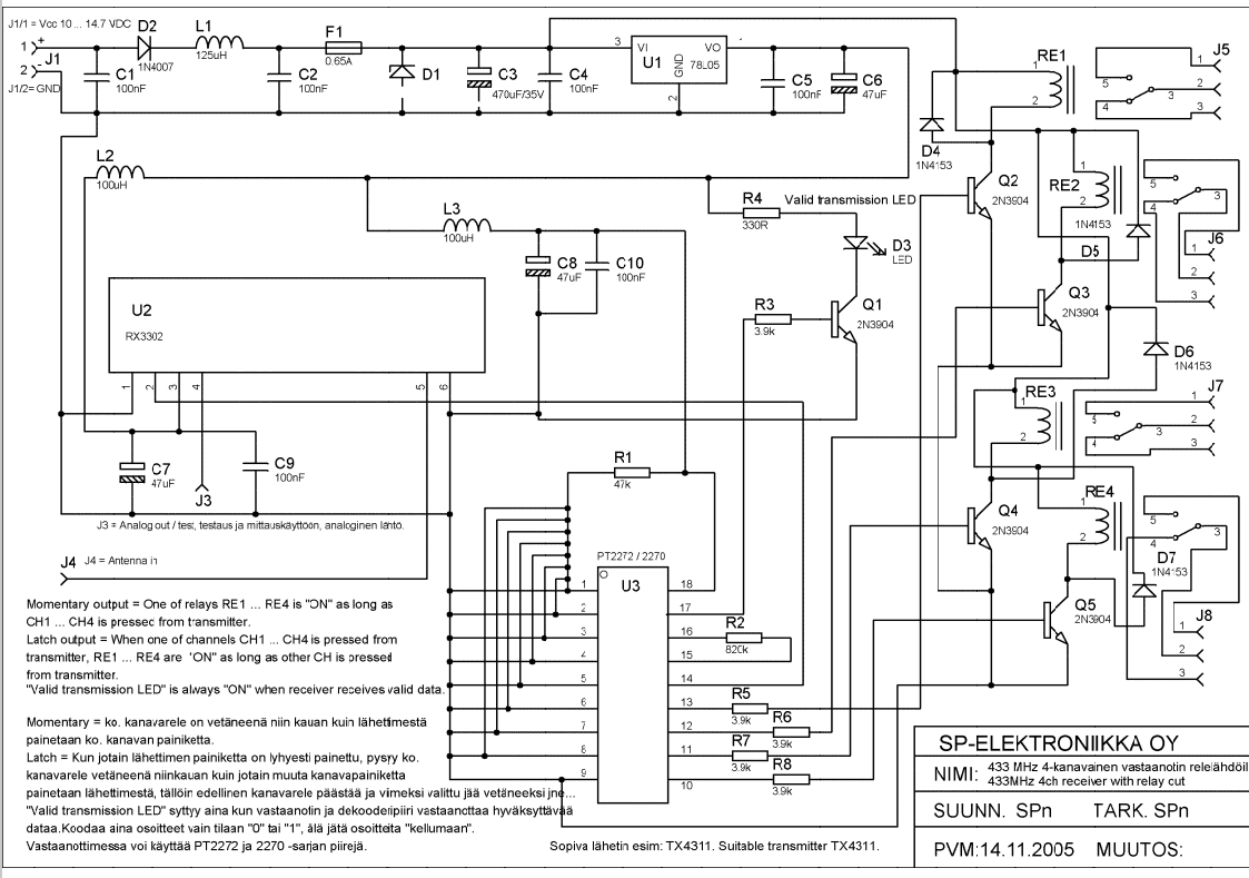
Momentary output: One of the relays RE1...RE4 is ON as long as CH1---CH4 is pressed from transmitter. Latch output: when one of channels CH1...CH4 is pressed from transmitter RE1...RE4 are ON as long as other CH is pressed from...
Place the transmitter approximately 10 feet away from an FM radio. Set the radio to a frequency between 89 and 90 MHz. Walk back to the FM transmitter and turn it on. Separate the windings of the coil by...
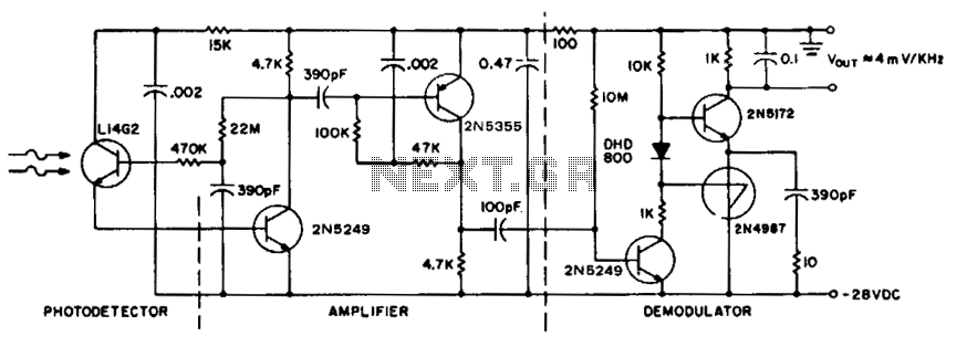
To achieve maximum range, the receiver should be constructed similarly to a radio receiver front end, as the signals received will exhibit comparable frequency components and amplitudes of the photodiode current. The primary limitation on the receiver's performance is...