
2 Watt FM Transmitter
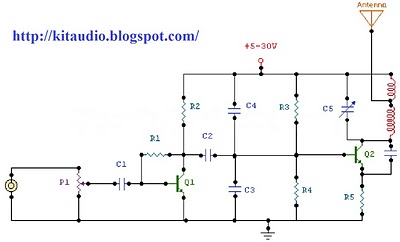
This RF oscillator circuit operates at a frequency near 100 MHz and is designed to amplify audio signals for transmission. The electret microphone serves as the input device, converting sound waves into electrical signals. These signals are then amplified by the first transistor, which is part of the audio amplifier stage. The amplified audio signal is critical for modulating the RF signal.
In the Hartley oscillator configuration, the tank circuit, consisting of an inductor (L1) and a variable capacitor (trimcap), is essential for generating the desired oscillation frequency. The inductor provides the necessary inductance, while the trim capacitor allows for fine-tuning of the resonant frequency. This tuning capability is crucial for ensuring that the oscillator operates efficiently at the target frequency of 100 MHz.
The modulation of the resonant frequency is achieved through the second transistor (T2), where the audio signal affects the base-emitter junction capacitance. As the audio signal fluctuates, it alters the voltage across the base of T2, thereby changing the junction capacitance. This variation in capacitance directly influences the resonant frequency of the tank circuit, allowing the RF oscillator to encode the audio signal onto the carrier wave.
Overall, this circuit exemplifies a classic application of RF technology, where audio signals are effectively transmitted over radio frequencies through modulation techniques, providing a foundation for various wireless communication systems. Proper component selection and circuit design are essential to achieve stable operation and optimal performance of the RF oscillator.The circuit is basically a radio frequency (RF) oscillator that operates around 100 MHz. Audio picked up and amplified by the electret microphone is fed into the audio amplifier stage built around the first transistor. Output from the collector is fed into the base of the second transistor where it modulates the resonant frequency of the tank circ
uit (L1 coil and the trimcap) by varying the junction capacitance of the transistor. Junction capacitance is a function of the potential difference applied to the base of the transistor T2. The tank circuit is connected in a Hartley oscillator circuit. 🔗 External reference
Related Circuits
Here I propose a project of an AB class power amplifier, at its simplest, assembled with common components (not very expensive), based on traditional diagrams: a symmetrical differential input stage, a cascode stage driver, and a MOSFET output stage....
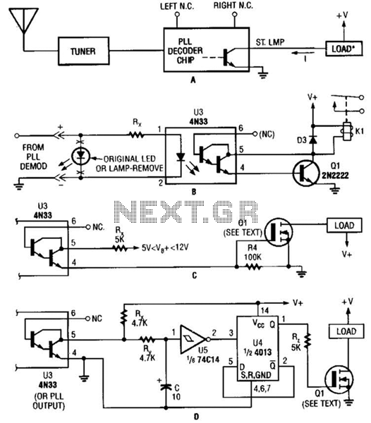
Several possible interface circuits are presented for use with a remote-control transmitter. The circuit labeled A demonstrates a typical FM stereo MUX decoder with a load connected directly to the open-collector output of a TA7343 PLL. The circuit labeled...
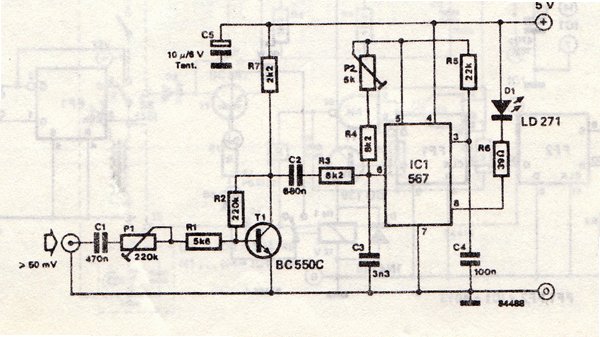
The transmitter is equipped with an LM567 tone decoder circuit. An audio signal (at least 50 mV peak-to-peak) is amplified with a transistor (T1) and then used to modulate IC1. The infrared transmitter frequency is adjusted with potentiometer P2...
This schematic for an experimental data transmitter utilizes optical fibers and a laser diode. The transmission frequency of the free-running oscillator is approximately 3 kHz. Resistor R5 may need to be adjusted to match the specifications of the laser...
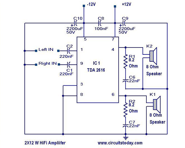
A simple Hi-Fi amplifier circuit diagram with a schematic for creating an audio amplifier, designed using the TDA 2616 integrated circuit (IC), which is a stereo power amplifier. It is suitable for use with radios, tape players, and televisions,...
This compact transmitter employs a Hartley oscillator configuration. Typically, the capacitor in the tank circuit connects to the base of the transistor; however, at VHF frequencies, the base-emitter capacitance of the transistor behaves like a short circuit, maintaining its...