
Good Quality 500M FM Transmitter

This FM transmitter circuit is engineered to deliver reliable performance for audio broadcasting applications. The circuit typically consists of several key components: an oscillator, a modulator, an amplifier, and an antenna.
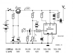
The oscillator generates a carrier frequency in the FM band, typically between 88 MHz and 108 MHz. This frequency is determined by the values of the capacitors and inductors used in the oscillator circuit. The modulator is responsible for varying the frequency of the carrier wave in accordance with the input audio signal, which is usually fed from an audio source such as a microphone or an audio player.
The amplifier boosts the modulated signal to increase its power output to around 200 mW, which is sufficient for achieving a transmission range of up to 500 meters under optimal conditions. The antenna, usually a simple dipole or monopole design, radiates the signal into the surrounding environment, allowing it to be received by FM radios within the specified range.
Power supply considerations are also essential for this circuit. A stable voltage source is required to ensure consistent operation, and the circuit may include voltage regulators to maintain the required operating voltage for the various components.
In summary, this FM transmitter circuit is suitable for applications requiring moderate-range audio transmission, providing a balance of performance and simplicity in design, making it an excellent choice for hobbyists and developers alike.Good Quality FM transmitter circuit for your amplifier, gives you a pretty good signal strength up to range of 500 metres having a power output of about 200 mW 🔗 External reference
Related Circuits
This transmitter project is a highly efficient, rugged, and simple low-power continuous wave (C.W.) unit delivering more than 10W. It is crystal-controlled with stabilized high tension (H.T.) and features a buffer stage between the crystal oscillator and power amplifier...
The most important part of this 88-108 transmitter is the Colpitts oscillator. Capacitors C3, C4, C5, C6, and diodes CD1 and CD2, along with inductor L1, determine the transmission frequency. The RF oscillator. The Colpitts oscillator is a type of...
The preamp featured has optional tone and balance controls which may be omitted if desired. The input switching may be extended if needed to accommodate more signal sources. In this version, no RIAA (phono) input is provided. See the...
This is an FM transmitter circuit that utilizes logic gates. The circuit features a radio frequency (RF) oscillator, which operates with a 10.7 MHz ceramic filter. The FM transmitter circuit is designed to modulate audio signals onto a carrier frequency...
These do-it-yourself FM transmitters are relatively simple to construct and provide a satisfying experience when music is played through the radio receiver. Comments and links to additional designs that are not included in the best list are welcome. FM transmitters...

The circuit was constructed using a few components powered by a 9 V battery to sense the presence of bugs transmitting within the frequency modulation. The circuit design utilizes a 9 V battery as the primary power source, making it...