
20 LED VU meter
Part List
R1-2=10Kohm C1=100uF 25V D1-19=LED 3 or 5mm any colour.
R3-4=10Kohm C2-5=10uF 25V D20-21=1N4148
R5-8-9=1Kohm C3-4=100nF 100V
R6=330Kohm C6=1uF 25V IC1=TL 072
R7=62Kohm IC2=LM3915
TR1=47Kohm Trimmer S1=mini Switch IC3=LM3916
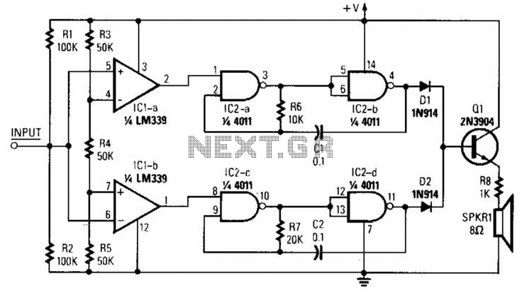
The described circuit is a level measurement system designed for acoustic signals, utilizing integrated circuits (ICs) from National Semiconductor. The circuit is structured around two main operational amplifiers, IC1 and IC2, where IC1 serves as an input stage for adaptation and amplification of the incoming signal. A trimmer potentiometer, TR1, is employed to adjust the gain of this first stage, allowing for fine-tuning of the input signal level to optimize performance.
The output from IC1 is fed into IC2, which performs half-wave rectification of the amplified acoustic signal. This rectification is crucial for converting the AC signal into a usable DC level that can be processed or displayed. The circuit includes a switch, S1, which allows the user to select the type of visual indication from the LED array, providing flexibility in output display options.
Resistors R6 and R7 play a significant role in setting the input signal level, which is specified to be 7.8V with a unity gain from the first stage (IC1). The design anticipates a 3 dB difference in signal levels between the LEDs D10 and D11, which indicates the dynamic range of the measurement system.
Power supply considerations are important in this design, particularly regarding the positive supply rail, which must be capable of providing sufficient current to prevent overload conditions, especially when driving the LED indicators. The inclusion of various capacitors (C1, C2, C3, C4, C5, and C6) serves to stabilize the circuit and filter any noise, ensuring accurate measurement and indication of the acoustic signal levels.
The component list specifies various resistors, capacitors, diodes, and ICs, including the TL072 for the operational amplifier and the LM3915 and LM3916 for LED bar graph and dot display drivers, respectively. This comprehensive design provides a robust solution for measuring and visually indicating acoustic signal levels in a variety of applications. A circuit of measurement of level based on a typical application of National. The circuit round the IC1 makes input adaptation and amplification with the trimmer TR1 [GAIN]. The circuit round the IC2 makes half-wave rectification of acoustic signal. With switch S1, we select the type of indication, that we will have from the LED. With the prices in resistances R6 and R7 that exists in the circuit, the level of signal, in the entry is 7.8V (gain of first stage IC1, is one), and the difference of level between the LED D10-11, should are 3 db. The positive department of supply, should have the possibility of giving more current, one and it is overloaded with the current of LED..
Part List R1-2=10Kohm C1=100uF 25V D1-19=LED 3 or 5mm any colour. R3-4=10Kohm C2-5=10uF 25V D20-21=1N4148 R5-8-9=1Kohm C3-4=100nF 100V R6=330Kohm C6=1uF 25V IC1=TL 072 R7=62Kohm IC2=LM3915 TR1=47Kohm Trimmer S1=mini Switch IC3=LM3916 🔗 External reference
Related Circuits
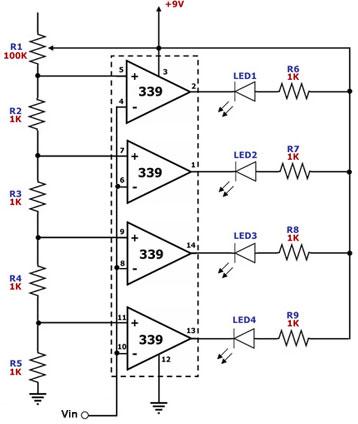
This circuit is designed as a simple LED bar graph voltmeter. Each operational amplifier in the LM339 quad package functions as a comparator, comparing the input voltage (Vin) to a series of fixed voltage levels that are proportional to...
A technique for measuring frequencies across a wide range with acceptable accuracy using a PC is described. This method involves measuring the period of a complete wave at low frequencies to calculate frequency from the measured time period. Cascaded...
One yet circuit with the known LM3915. It does not differ in a lot of points from other applications with same IC. The circuit accosted in those who they want a Vumeter that will be connected in the exit...
The circuit designed for distortion measurements eliminates the fundamental frequency of 1 kHz, enabling the assessment of the residual harmonic levels. Initially, a true RMS meter is employed to measure the 1-kHz input level (E^) by positioning the switch...
The circuit uses independent timers to flash two light emitting diodes. Any time that light emitting diode D1 is lit, light emitting diode D2 will be switched off. Light emitting diode D3 is on if both D1 and D2...
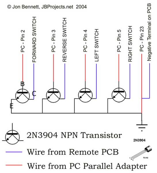
This project article was originally written in 2004 when most computers had parallel ports. This is no longer the case, so much of this information is now outdated. The Mini RC Car Project has been one of the most...
Warning: include(partials/cookie-banner.php): Failed to open stream: Permission denied in /var/www/html/nextgr/view-circuit.php on line 713
Warning: include(): Failed opening 'partials/cookie-banner.php' for inclusion (include_path='.:/usr/share/php') in /var/www/html/nextgr/view-circuit.php on line 713