
Vu Meter For Amplifiers

Part List
R1=See Text and Picture1 IC1=LM3915 D9=Led Yellow 5mm
R2=10 Kohms IC2=LM317T [On Heatsink] D10=Led Red 5mm
R3=1.2 Kohms TR1=15 Kohms Multiturn Trimmer S1=2dip Switch
R4=8.2 Kohms D1=1N4002 J1=3pin 2.54mm step connector
R5=See Text [2W] D2....D8=Led Green 5mm
R6=270 ohms C2-3-4=100nF 100V MKT 5%
C1=100uF 25V C5=22uF 25v.
The described circuit utilizes the LM3915 integrated circuit, which functions as a visual audio level indicator or VU meter. This device is particularly well-suited for applications where an audio signal needs to be visually represented, such as at the output of a power amplifier. The circuit can be configured to accommodate various amplifier output levels by adjusting the resistance value of R1 according to a specified table. If the calculated resistance does not match standard values, users are advised to select the nearest standard resistor or to combine resistors in series or parallel to achieve the desired resistance value.
The circuit supports a variety of LED configurations, allowing for customization of the visual output. The switch S1 enables the user to toggle between two modes: bar graph mode (when the switch is closed) and dot mode (when the switch is open). In bar mode, all LEDs are illuminated, resulting in higher current consumption, which can reach up to 150 mA.
For dual-channel amplifiers, two identical circuits may be required, one for each channel, ensuring that both channels are represented visually. The circuit operates on a supply voltage of +12 volts, which can be sourced from the existing power supply of the power amplifier. Since many power amplifiers operate at higher voltages, a voltage attenuation stage is necessary to step down the voltage to the required level. This is achieved through the use of the LM317T voltage regulator (IC2), which should be mounted on a heatsink due to the significant voltage drop it manages, which can lead to increased heat generation.
Resistor R5 plays a crucial role in limiting the input voltage to IC2, ensuring it remains above +16 volts for optimal operation. The resistance value for R5 can be calculated using Ohm's Law, based on the voltage drop across it and the desired current. For example, with a power amplifier voltage of +50 volts, the drop across R5 would be 34 volts when accounting for the minimum input voltage required by IC2. Depending on the average current draw of the circuit, which is typically around 50 mA, R5 can be calculated as approximately 680 ohms with a power rating of 2 watts. It is advisable to position the resistor away from the PCB to manage heat dissipation effectively.
The adjustment of IC2's output voltage is facilitated by the trimmer potentiometer (TR1), which should be calibrated before the LM3915 (IC1) is connected to ensure proper functionality. If a stable +12V supply is available from the power amplifier, R5, IC2, and associated components can be omitted, simplifying the circuit design.
The part list includes various resistors, capacitors, diodes, and LEDs, which are essential for the circuit's operation and can be selected according to specific design requirements. This schematic serves as a robust foundation for creating a customizable VU meter suitable for various audio applications.One yet circuit with the known LM3915. It does not differ in a lot of points from other applications with same IC. The circuit accosted in those who they want a Vumeter that will be connected in the exit of power amplifier. It can be adapted his sensitivity so as to it works with amplifiers that have different out power, enough we change the R1 price of according to Table 1.
The price that will be found if it does not correspond in standard resistance price, it should selected the next standard price or if you want the biggest precision it should you put resistances in series or parallel so that you achieve the price. Can use various types Leds round or square, so that you take the optical and aesthetic result that you want.
With switch S1 selects if the Vumeter works as bar or dot. In the place ON [switch closed] the operation is bar and in place OFF [switch open] the Led operation is Dot. In the place Bar the consumption goes up, because work all the Led and it can reach until 150mA. For amplifier with two channels obviously it?s that it will be supposed made two same circuits, one for each channel.
The voltage circuit supply is +12Volts. The reception of this supply should become from the existing power supply of power amplifier. Usually the power amplifiers work with supply bigger than +12Volts that it needs the circuit. For this reason added one stage of voltage +Vp attenuation in +12Volts. This becomes with the stage that is found in the discontinued line and with the IC2. That is a regulated stabilizer. The use of small heatsink is essential because the voltage differences of input ? output are big so that we have growth of high levels of temperature. The use of R5 helps in the fall of voltage so that goes down the voltage in the IC2 input in lower levels. The calculation of this resistance price becomes empirically using the Ohm law. The voltage in the IC2 input should it is bigger than +16Volts. For example if the voltage of power amplifier is for example +50Volts it will be supposed we have voltage fall 50-16=34 Volts above in R5.
For current with mean 50mA that it wants circuit [can reach until 150mA] the price of R5= V/I=34V/0.05A=680 ohms 2W. Perhaps it needs boost or decrease this price after tests. Because the resistor heat good is it placed in some distance from PCB. Her regulation process of IC2 with the TR1 good is it becomes first without exists the IC1. For this reason it should it?s placed in a base. If you have benefit possibility of continuous voltage +12V from some point of power amplifier, obvious is to leave out the R5, the IC2 and the components that are found in the discontinued line.
. Part List R1=See Text and Picture1 IC1=LM3915 D9=Led Yellow 5mm R2=10 Kohms IC2=LM317T [On Heatsink] D10=Led Red 5mm R3=1.2 Kohms TR1=15 Kohms Multiturn Trimmer S1=2dip Switch R4=8.2 Kohms D1=1N4002 J1=3pin 2.54mm step connector R5=See Text [2W] D2....D8=Led Green 5mm R6=270 ohms C2-3-4=100nF 100V MKT 5% C1=100uF 25V C5=22uF 25v. 🔗 External reference
Related Circuits
This LED thermometer is designed for in home use, to read temperatures between about 60 and 78 degrees Fahrenheit. It is based around a precision temperature sensor IC, the LM34DZ. This sensor require no calibration and can measure temperatures...
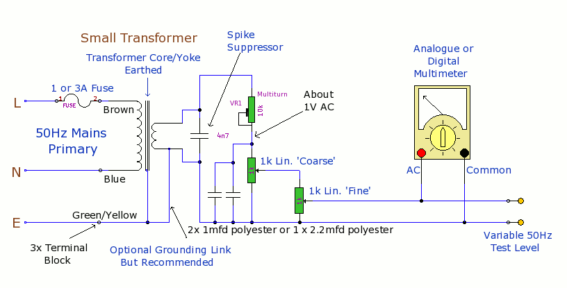
The purpose of this prototype unit is to eliminate the need for an oscillator. It provides a mains-derived and fully variable 50 Hz AC voltage, adjustable down to millivolts for comparison and accuracy testing of two or more parallel-connected...
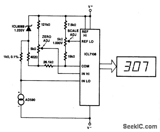
This circuit allows for zero adjustment as well as slope adjustment. The ICL8069 brings the input within the common-mode range, while the 5 K pots trim any offset at 218 °K (-55 °F) and set the scale factor. The...
This is an electric thermometer circuit composed of the LM134. In the circuit, the voltage or current output by the LM134 is proportional to the thermodynamic temperature, which can be read on a 100 µA meter. The test temperature...
The availability of affordable digital multimeters and integrated circuit temperature sensors has made it straightforward to create a sensitive and accurate digital thermometer suitable for various experiments at home or in amateur laboratories. Two temperature sensors that simplify this...
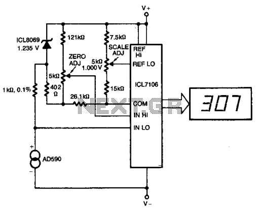
The ICL8069 brings the input within the common-mode range, while the 5 k ohm pots trim any offset at 218° (-55°C) and set the scale factor. This circuit allows for zero adjustment as well as slope adjustment. The ICL8069 is...