
200 Watt audio power amplifier
It is possible to use the MOSFET output stage PCB which is also reproduced on the site, but take care with the thermal dissipation of the output transistors (this circuit is perfect for power of 100 Wrms under 8 ohms or 155 Wrms under 4 ohms). It is possible to use two PCBs in parallel to double the number of output transistors; do not place the limitation diodes, the fuses, and the RC output circuit on the second PCB. The power transistors must be assembled on a heatsink with a thermal resistance less than 1 °C/W. They must also be electrically insulated from the heatsink by using a mica insulator + heat-conducting compound or a silicone insulator. The ground (earth) points of PCBs and loudspeaker ground (earth) must compulsorily be connected in star with the 0 Volts of the PSU. Bandwidth is limited from 5 Hz to 53 kHz (at -3 dB) by the input module (C1, R1, C2, R2). It can be modified according to the application desired. It is useless to increase the bandwidth to the bottom (bass) because little useful signal is present at the bottom of the spectrum. In public address sound systems, the bandwidth is often limited between 20 and 35 Hz. The loudspeakers are thus protected against too high extreme-bass signals and some more power is available for the remainder of the spectrum.
The AB class power amplifier described utilizes a symmetrical differential input stage, which enhances the common-mode rejection ratio, thereby improving the overall sound quality. The cascode driver stage further increases the gain while minimizing the Miller effect, which can degrade high-frequency performance. The output stage employs MOSFET transistors, known for their high efficiency and thermal stability, allowing the amplifier to deliver substantial power without excessive heat generation.
The power supply, consisting of a 625 VA transformer, is designed to provide stable voltage rails of ±70 volts, ensuring that the amplifier can handle dynamic peaks in audio signals without distortion. The six 4700 µF reservoir capacitors help maintain voltage stability and reduce ripple, contributing to the amplifier's high signal-to-noise ratio of 112 dB.
Thermal management is critical in this design. The requirement for a heatsink with a thermal resistance of less than 1 °C/W ensures that the output transistors operate within safe temperature limits, enhancing reliability and longevity. The use of mica or silicone insulators allows for effective thermal transfer while maintaining electrical isolation from the heatsink.
The circuit's bandwidth limitation from 5 Hz to 53 kHz is beneficial for audio applications, ensuring that the amplifier operates efficiently within the audible range while protecting loudspeakers from low-frequency signals that could cause damage. The option to adjust the quiescent current via potentiometer P1 enables fine-tuning of the amplifier's performance, allowing for optimal operation based on speaker characteristics and listening environments.
Overall, this AB class power amplifier design combines traditional engineering principles with modern components to deliver a reliable and high-performance audio solution suitable for various applications, including home audio systems and public address setups.Here i propose a project of an AB class power amplifier, at its simplest, assembled with common compoments (not very expensive), based on traditional diagrams : a symmetrical differential input stage, a cascode stage driver and a MOSFET output stage. The printed circuit board is very compact , and is composed of two subsets : the command stage and the output stage.
All resistors are 1/4 watt 1 % metal film (except if otherwise stated). Constant current sources of +/- 1 mA are carried out around T5 and T6. The diodes D1 to D6 allow the use of low noise transistors type BC550C and BC560C, the transistors T7 to T10 form the stage driver. The potentiometer P1 allows the adjustment of the quiescient current to 100 mA per output transistor.
The symmetrical power supply is entrusted to a large transformer of 625 VA, 2 * 51 volts + bridge rectifier and 6 reservoir capacitors of 4700 µF, which gives an output voltage of + and - 70 volts per rail. The output power is 200 Wrms under 8 ohms or 350 Wrms under 4 ohms. Distortion is lower than 0,02 %, damping factor is better than 300, signal-noise ratio is 112 db (balanced A at full power), the input sensitivity is 1,2 volts (200 W under 8 ohms).
It is possible to use the MOSFET output stage PCB which is also reproduced on the site, but take care with the thermal dissipation of the output transistors (this circuit is perfect for power of 100 Wrms under 8 ohms or 155 Wrms under 4 ohms). It is possible to use two PCBs in parallel to double the number of output transistors, do not place the limitation diodes, the fuses and the RC output circuit on the second PCB.
The power transistors must be assembled on a heatsink with a thermal resistance less than 1 ° C/W. They must also be electrically insulated from the heatsink by using a mica insulator + heat-conducting compound or a silicone insulator. The ground (earth) points of PCB's and loudspeaker ground (earth) must compulsorily be connected in star with the 0 Volts of the PSU.
Bandwidth is limited from 5 Hz to 53 Khz (at - 3 db) by the input module (C1, R1, C2, R2). It can be modified according to the application desired. It is useless to increase the bandwidth to the botton (bass) because little useful signal is present at the bottom of the spectrum. In public address sound systems the bandwidth is often limited between 20 and 35 Hz. The loudspeakers are thus protected against too high extreme-bass signals and some more power is available for the remainder of the spectrum.
🔗 External reference
Related Circuits
This regulated power supply is adjustable between a few volts and 15V using P1, while P2 is used to set the upper limit at 15.0V. The value of R6 is calculated as 0.7V divided by Imax, where Imax represents...
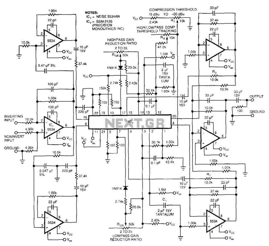
This 2-band compressor separates audio into high and low frequencies, allowing for independent adjustments of each band. Two active filters drive the two halves of a dual voltage-controlled amplifier/rectifier integrated circuit (IC). Each section features a dynamic range exceeding...
A PoE Plus power level of 30 W can be achieved by utilizing an external MOSFET along with a controller that is compatible with the older standard. Power over Ethernet (PoE) technology enables the delivery of electrical power along with...
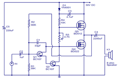
This is a 10W MOSFET audio amplifier circuit that operates from a single power source. Single rail configurations are seldom used in Class B power amplifiers; however, they are suitable for low-power applications like this one. This circuit design...
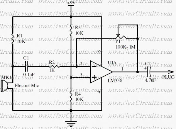
This circuit will be useful if you have an electret microphone that produces a low audio (sound) level and you want to connect it to an amplifier or something like it. The circuit boosts the microphone output voltage to...
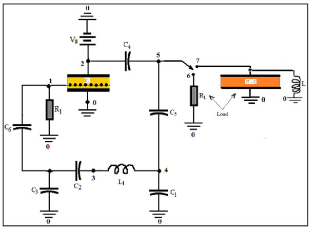
COMSOL's integration of SPICE® elements into its finite element method (FEM) allows for direct modeling of oscillators. In this approach, the triode and load are described using FEM, while all other circuit components are simulated with SPICE®. This modeling...