
PoE+ Circuit Delivers 13W to 70W for Powered Devices (PDs)
Power over Ethernet (PoE) technology enables the delivery of electrical power along with data over standard Ethernet cables, allowing devices such as IP cameras, VoIP phones, and wireless access points to receive power without the need for separate power supplies. The PoE Plus standard, defined by IEEE 802.3at, extends the capabilities of the original PoE standard (IEEE 802.3af) by allowing for a maximum power output of 30 W per port.
To implement a PoE Plus system capable of delivering this power level, an external MOSFET is integrated into the circuit design. The MOSFET serves as a switch that regulates the flow of power to the powered device (PD). The controller, designed for compatibility with the older PoE standard, manages the detection and classification of the powered device, ensuring that the appropriate power level is supplied.
The circuit typically includes a power sourcing equipment (PSE) component that interfaces with the Ethernet cable, supplying power through the spare pairs or the data pairs, depending on the wiring configuration. The external MOSFET is controlled by the PSE, which adjusts the gate voltage to modulate the power delivered to the PD based on its requirements.
In summary, the combination of an external MOSFET and a compatible controller allows the implementation of a PoE Plus system that meets the 30 W power requirement, enabling efficient power delivery for a variety of networked devices while adhering to the established standards.It is possible to implement a PoE Plus-required power level of 30 W, with the aid of an external MOSFET and a controller designed for the older standard.. 🔗 External reference
Related Circuits
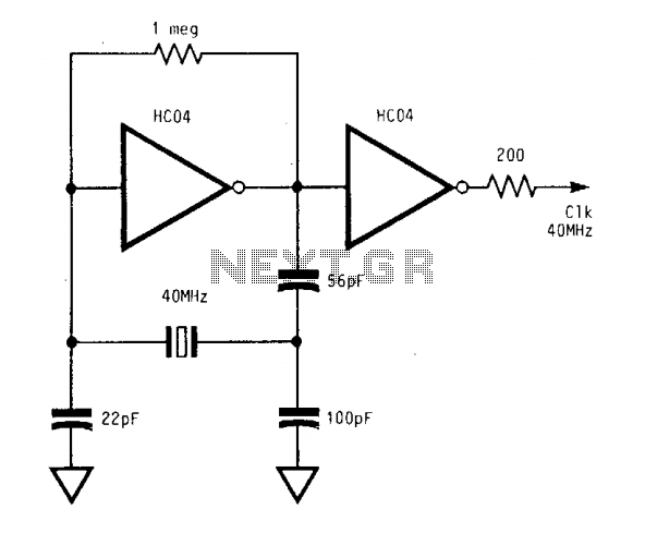
The circuit operates reliably from below 1 MHz to above 400 MHz. With a supply voltage (Vcc) of 5 V, the output of the second inverter achieves a full swing from 0 V to 5 V. These significant logic...
The bicore is the basis of advanced BEAM. Most intermediate to advanced BEAM robots are built off of the bicore. Uses go all the way from photovores to servo motor drivers to walkers. What it is is basically just...

This is the design of a bias current compensation circuit. This circuit can operate with medium wattage source resistances while maintaining a minimal increase in the equivalent offset voltage. It is based on the LM11 operational amplifier. The circuit...
The 1-megohm resistor protects the FET from potential damage caused by accidental sparks to its gate lead. The circuit functions adequately without this resistor; however, it is advised not to intentionally apply a charge to the gate wire using...
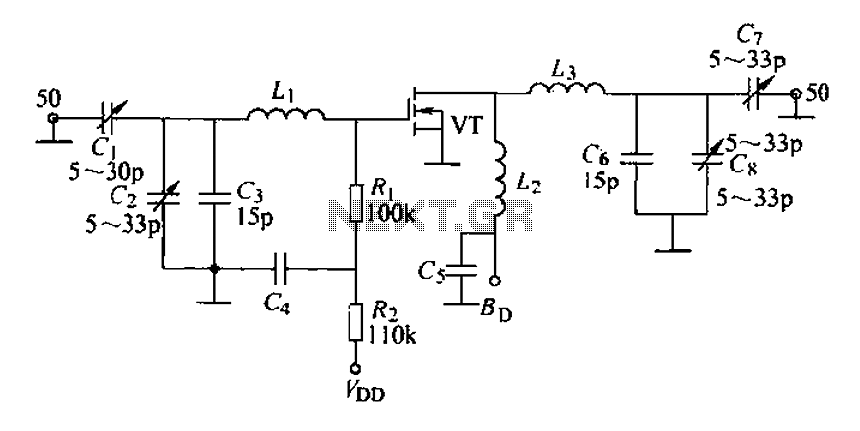
A 175 MHz high-frequency amplifier circuit utilizing a field-effect transistor (FET) is presented. The field-effect transistor used is the 3D04H, along with its associated components and parameters. The 175 MHz high-frequency amplifier circuit is designed to amplify signals in the...
%2Bdecoder%2BCircuit%2Bschematic%2Busing%2BM8870.png)
This DTMF (Dual Tone Multi Frequency) decoder circuit identifies the dial tone from the telephone line and decodes the key pressed on the remote telephone. For the detection of DTMF signaling, the IC MT8870DE, a touch tone decoder IC,...
Warning: include(partials/cookie-banner.php): Failed to open stream: Permission denied in /var/www/html/nextgr/view-circuit.php on line 713
Warning: include(): Failed opening 'partials/cookie-banner.php' for inclusion (include_path='.:/usr/share/php') in /var/www/html/nextgr/view-circuit.php on line 713