
Stabilized Adjustable Power Supply 0-15V/5A
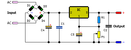
This regulated power supply circuit is designed to provide a stable voltage output that can be finely tuned to meet specific requirements. The adjustment of output voltage is facilitated by potentiometer P1, allowing the user to set the desired voltage anywhere from a minimum value up to a maximum of 15V. The second potentiometer, P2, serves to establish the upper voltage limit, ensuring that the output does not exceed 15.0V during operation.
The resistor R6 plays a crucial role in current regulation, where its value is determined by the formula R6 = 0.7V / Imax. This relationship indicates that as the maximum current (Imax) increases, the resistance value must decrease correspondingly to maintain the voltage drop across R6 at 0.7V. For a maximum current of 5A, R6 is specified to be 0.14 ohms. This low resistance is necessary to allow sufficient current flow while maintaining voltage regulation.
Thermal management is an essential consideration in the design of this power supply, particularly for the transistors T1 and T2. Due to the inherent power losses that occur when the output voltage is low and the current is at its maximum level, these components generate considerable heat. Therefore, the inclusion of heatsinks is critical to dissipate this heat effectively and prevent thermal overload.
To further enhance efficiency and reduce power losses, a lamp can be connected in parallel with the output load. This configuration allows for better energy distribution and can help manage the thermal characteristics of the circuit. The lamp acts as a load that can absorb excess power, thereby reducing the stress on the transistors and improving the overall performance of the power supply.
In summary, this regulated power supply circuit is a versatile solution for providing adjustable voltage levels, with careful attention paid to component selection and thermal management to ensure reliable operation under varying load conditions.This regulated power supply can be adjusted between a few volts and 15V with P1 and with P2 adjust the upper limit ( 15. 0V ). R6 value is 0. 7V / Imax where Imax is the maximum current. At Imax = 5A, R6 is 0. 14 © T1 and T2 must have heatsinks because power losses are great at a low output voltage and a Imax equal current but you can connect the lam
p L to reduce this losses. 🔗 External reference
Related Circuits
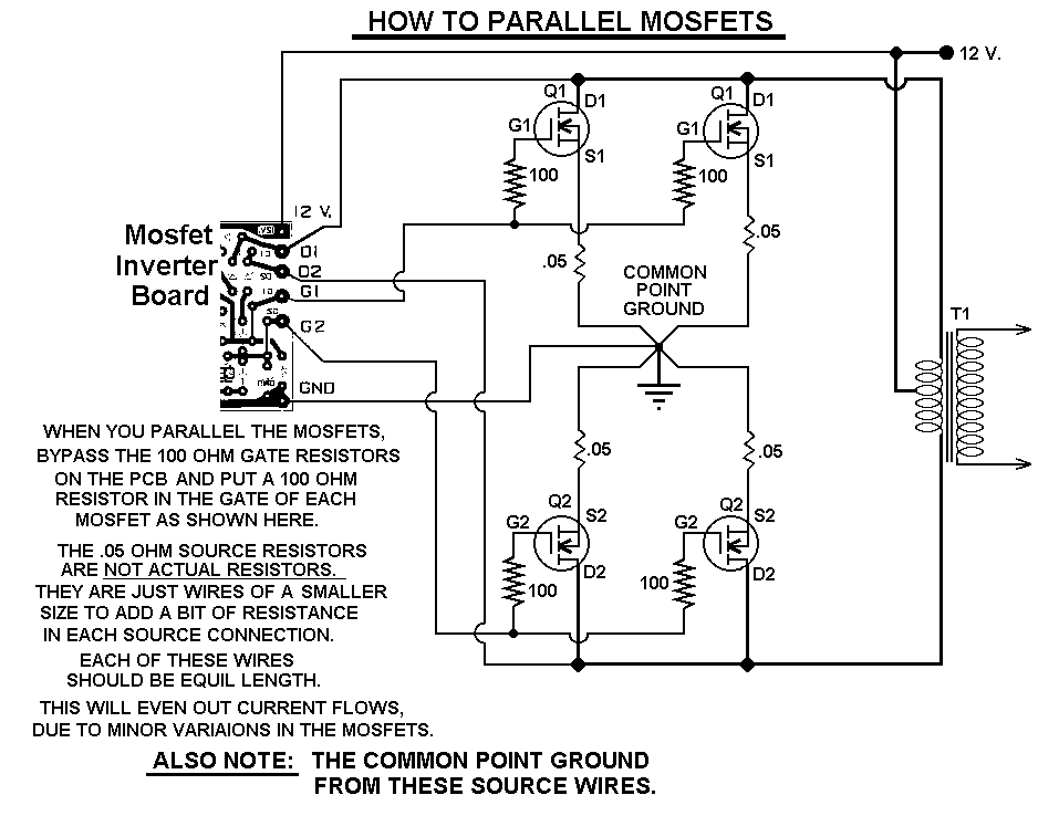
This 1000-watt power inverter circuit diagram is based on the MOSFET RF50N06. For increased power output, additional MOSFETs can be paralleled with the RF50N06. These MOSFETs are rated for 60 volts and 50 amps. It is essential to connect...

The unit is designed around a standard operational amplifier and utilizes easily obtainable components. The reverse-engineered circuit diagram of the Anatek 50-1S variable power supply is shown below. The layout of the circuit board does not appear to be...
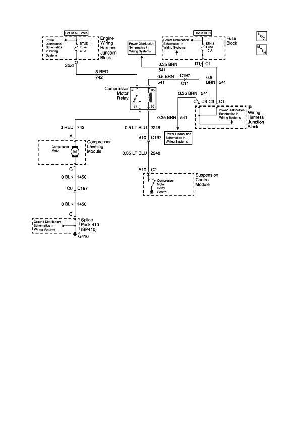
The physical location of the compressor relay is needed, as well as instructions on how to test the pressure sensor on the plastic tank of the compressor assembly. The exact location of the relay has not been confirmed, but...
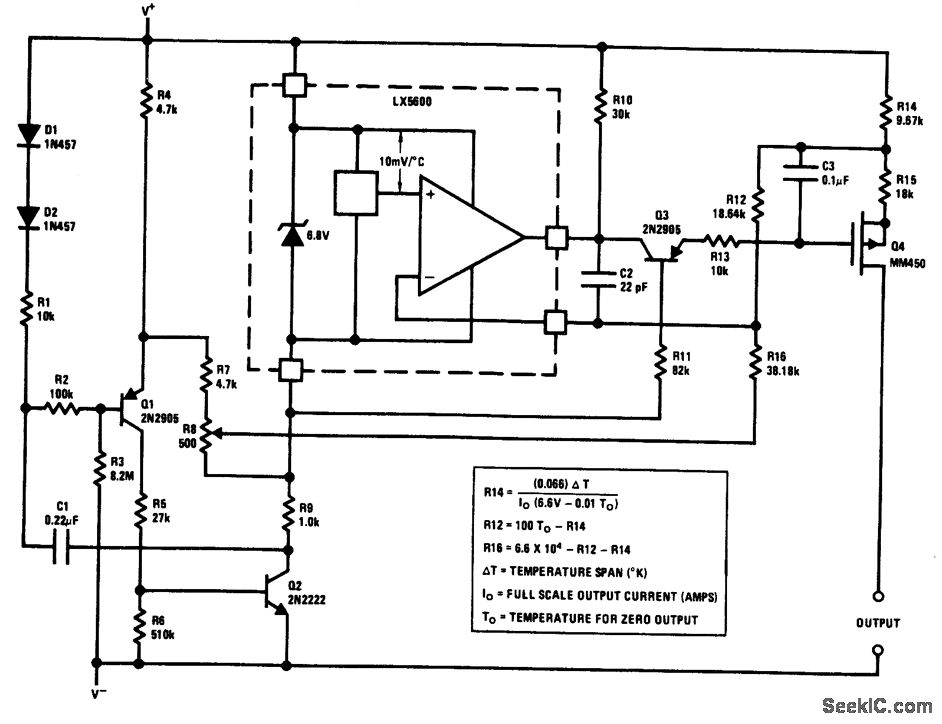
The output of this circuit is a current that is proportional to temperature, which can be utilized to drive a meter for direct readout. Alternatively, a resistor or operational amplifier can be employed to obtain a voltage output. The...
The simple method to power your projects is illustrated in the circuit diagram of a regulated power supply. This compact power supply delivers a stable voltage. This regulated power supply circuit is designed to convert an unregulated input voltage into...
I didn't realize till the other day that I have never shown a circuit for a standard power supply. Shown below is a supply that will use any of the LM78XX series of voltage regulators. The transformer in the...