
20dB VHF Amplifiers
The preamplifier circuit is composed of two identical amplification stages, each utilizing an NPN transistor in a common emitter configuration. This arrangement allows for effective amplification of weak signals while maintaining a broad frequency response. The circuit design emphasizes the importance of component selection, particularly the transistors, which should have similar characteristics to ensure consistent performance across both stages. The use of ceramic capacitors for inter-stage coupling is critical, as they help maintain signal integrity while minimizing losses at high frequencies.
The gain provided by each stage is approximately 10dB, resulting in a total gain of around 20dB for the entire circuit. This gain is sufficient for many applications, especially in the VHF range where television signals are prevalent. The amplifier is capable of operating effectively up to 500MHz, making it versatile for various RF applications.
To optimize the amplifier's performance, it is essential to ensure that the power supply is stable and capable of delivering the required 12V. The design also accounts for the need to adjust resistor values based on the specific transistors used, ensuring that the circuit operates within its intended parameters. The low current consumption of the circuit, typically only a few milliamperes, makes it suitable for battery-powered applications.
In summary, this preamplifier circuit is designed for efficient signal amplification in the VHF range, utilizing a straightforward and effective design that can be easily assembled with commercially available components. Its broad frequency response and adequate gain make it a valuable tool for various RF applications, particularly in the realm of television signal amplification. Proper assembly, component selection, and housing in a metal enclosure will ensure optimal performance and longevity of the circuit.The preamplifier offers 20dB in all the region of VHF and it still can reach also their 500MHZ. The amplifier is a circuit of high frequency RF with distinguishable materials. The amplifier as circuit strengthens the tendency of signal with concrete aid, depending on the frequency of signal. If the frequency of signal is included in the limits of spectrum of frequencies of amplifier, then it is strengthened, otherwise it is downgraded. Each amplifier of this category, accordingly with his designing, strengthens a concrete region of frequencies and obeys in same characteristics. The one that to you we present today concerns the regions of VHF where they exist and the corresponding television stations for channels 5 until 12.
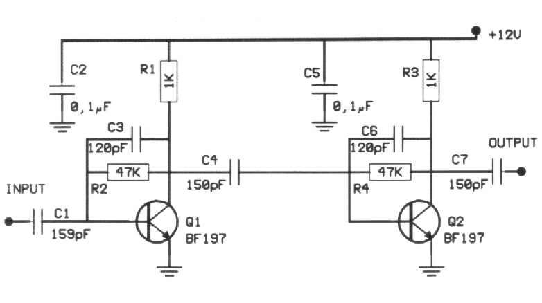
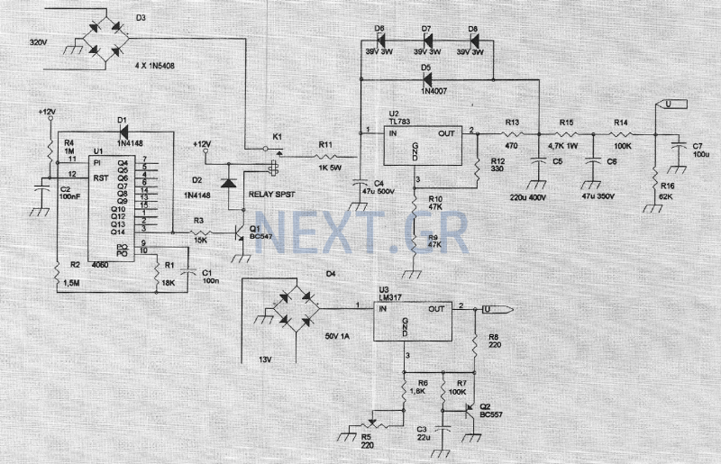
His circuit he is enough simple, so that it is made easily with materials that exist in the trade. It is based on transistors with aid until the 500MHZ. The type of transistor can be BF197 or some other. In form 1 appears the theoretical circuit of amplifier. As we see it is constituted from two similar circuits (rungs). In this circuits are not included in joint action circuits. With that way is covered a wide spectrum of frequencies, without is differentiated abruptly the aid as for the frequency. With this provision we have smaller gain but big breadth of frequencies. The two rungs are same, with the same prices of materials and each rung offer aid roughly 10dB. The transistors and the remainder materials, because the industrial manufacture, have almost the same characteristics.
Associates the particular characteristics of demagogues are altered mainly the aid of rung. Each rung uses a transistor of type npn in provision of common emitter that functions in order A. his rungs works in provision of common emitter with null resistance in emitter. In each rung a network of resistances between the collectors and the bases polarize the transistors and ensures the operation of circuit. The junction between the rungs becomes via ceramic capacitors of small capacity from 0, 1nF until 0, 22nF (at preference ceramic).
In the place of two rungs we can try various transistors of independent company or even different between them. The circuit of course cannot work with all of them. The tendency of catering should emanate from stabilised power supply with tendency 12V. Depending on the tendency of catering and the type of transistor, in each rung of amplifier it needs enter also different resistances.
Force of expense, under conditions of high excitation it can exceed the 1 mW The total aid of circuit, according to the elements of transistors, reaches 20dB. Enough aid for a lot of applications. The amplifier is drawn in order to it has big response of frequency up to 0, 5Ghz. According to the particular characteristics of manufacture, the better application that we could to you propose for this designing would be the aid of television signal emanating from a small transmitter of television or the preamplifier of a frequency meter.
The assembly of amplifier is realised above in printing form 2. In this you will place all the materials according to form 3. The manufacture, in order to it works right it needs one small stabilised power supply 12V. The consumption of circuit is small hardly some mA. The resistance en line with the collector is 10 000. When you finish the construction and the control of manufacture, place the PCB in metal box of suitable dimensions. 🔗 External reference
Related Circuits
Another version of the 1W VHF amplifier for the FM transceiver is presented. It is essentially the same version since achieving 1W output power has not yet been realized. Recent tests were conducted using a 2N2553 and a 2N2866...
A low-power VHF TV transmitter is an essential tool for video enthusiasts, allowing the transmission of signals from a VCR to any television in a home or backyard setting. This device enables the convenience of watching movies by the...
Most of us don't have the luxury of building a 1/4, 1/2 or even a 5/8 wavelength vertical antenna for HF. We have to settle for something a little shorter. (A lot shorter, in the case of people following...
The amplifier feeding the final amplification stage operates with unstabilized voltage. The output stage, utilizing push-pull operation, exhibits significant rejection of the supply voltage. However, the earlier stages do not provide the same level of rejection, resulting in unwanted...

These circuits are useful for video applications up to 10 MHz. The 3.3-pF capacitors serve as compensation capacitors. The capacitors connected to pins 7 and 4 act as bypass capacitors to prevent self-oscillations. Figure 76-18(a) illustrates a non-inverting configuration,...
Unlike conventional small-signal methods, employing large-signal, time-domain design techniques facilitates the creation of low-noise grounded-base oscillators suitable for VHF/UHF applications. The development of low-noise grounded-base oscillators for VHF/UHF applications presents unique challenges and opportunities. By utilizing large-signal, time-domain design techniques,...