
High Voltage Power Supply for Valve Preamplifiers
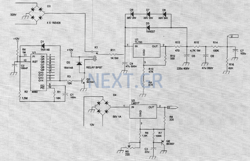
The circuit is depicted in the theoretical schematic. The alternating voltage is rectified using four 1N5408 diodes, which can withstand 1000V and 3A. Following this, a relay is activated after approximately one minute. The delay timer comprises a complete CD4060, which features an internal oscillator and serves as a voltage divider. Its outputs switch to 'High' once the desired time has passed. After this period, the integrated circuit ceases oscillation and maintains its final state due to the positive voltage present on the oscillator. This delay allows sufficient time for the lamp filaments to heat up and be ready for operation. A capacitive load of 50 µF, formed by two 100µF/250V capacitors in series, is introduced next. These capacitors are followed by a 1.5K resistor, which reduces the high voltage and also acts as a filter, suppressing noise and smoothing the voltage. Voltage stabilization is achieved using a specialized high-voltage integrated circuit, the TL783, which can handle 0.5A with a maximum input-output voltage difference of 120V. Three zener diodes and a diode connecting the output to the input of the integrated circuit protect against reverse and overvoltage. The output voltage is determined by the resistor values connecting the integrated output to ground. Additional resistors and capacitors are included to create RC disconnection circuits, which define the desired characteristics at the capacitor and resistor terminals. Additionally, the same board contains a circuit with an LM317 and associated components that provide a constant voltage of 12V for the preamplifier lamp filaments.
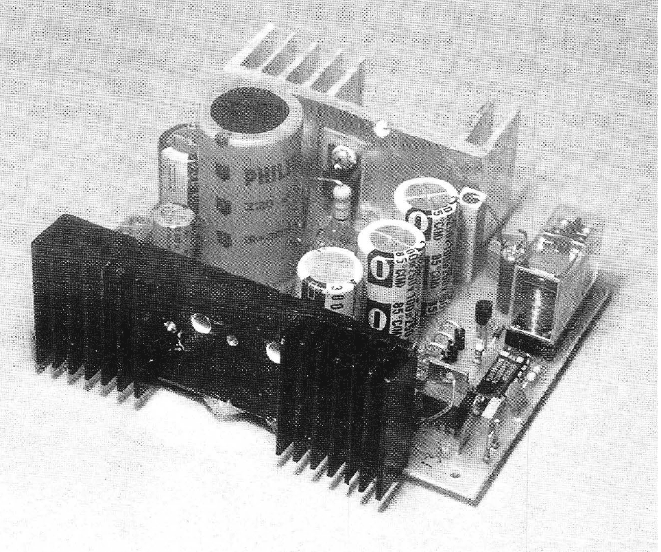
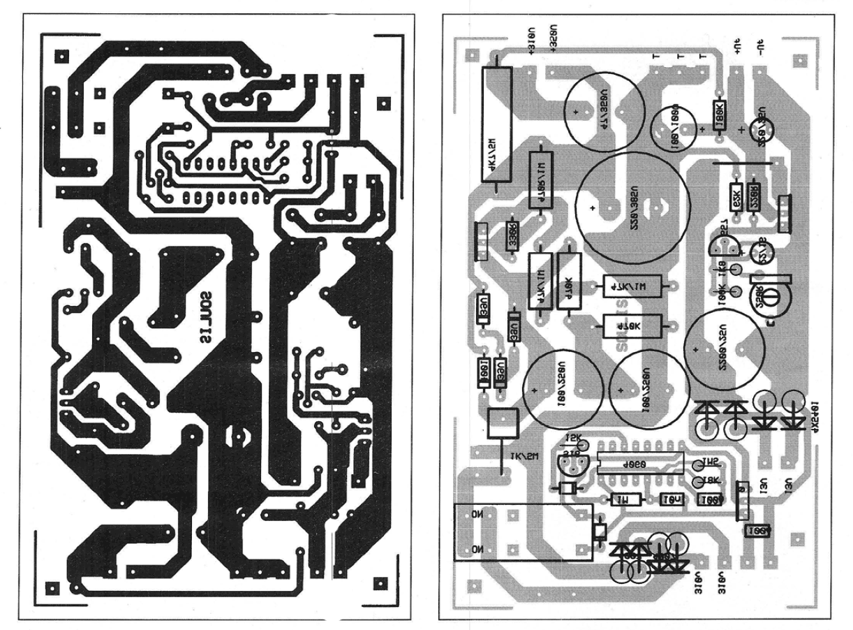
The construction is performed on a designated board, ensuring all components are placed correctly with respect to the polarity of diodes, capacitors, and integrated circuits. Pins are attached to the output terminals. Once construction is complete, the circuit should be powered with the appropriate voltage. After approximately one minute, the relay will arm, providing the desired high voltages. A trimmer is used to set the output to a constant 12V for the filament supply.
Components:
- C1: 100nF
- C2: 100nF
- C3: 22µF
- C4: 47µF 500V
- C5: 220µF 400V
- C6: 47µF 350V
- C7: 100µF
- D1, D2: 1N4148
- D3: 4 x 1N5408
- D4: 50V 1A
- D5: 1N4007
- D6, D7, D8: 39V 3W
- K1: SPST Relay
- Q1: BC547
- Q2: BC557
- R1: 18kΩ
- R2: 1.5MΩ
- R3: 15kΩ
- R4: 1MΩ
- R5, R8: 220Ω
- R6: 1.8kΩ
- R7, R14: 100kΩ
- R9, R10: 47kΩ
- R11: 1kΩ 5W
- R12: 330Ω
- R13: 470Ω
- R15: 4.7kΩ 1W
- R16: 62kΩ
- U1: CD4060
- U2: TL783
- U3: LM317
Caution is advised during testing, as high voltages present in the circuit can be dangerous.The amplifier feeding to the final amplification stage is performed with unstabilized voltage. The output stage, due to push-pull operation, has a large rejection of the supply voltage. The various other steps, however, do not have the same rejection and introduce unwanted noise. So the pre-amplification stage is good to be powered with a stabilized voltage, just as it is with transistors. With this construction we will fill the gap that exists by guiding you the way you can achieve 350V and 310V voltages needed for the preamplifier as well as the way you can have any high voltage you need.
The circuit
The theoretical part of the circuit is shown in Figure 1. As you can see, the alternating voltage is rectified with 4 diodes 1N5408 which resist 1000V and 3A. Then a relay is activated which is activated after about 1 minute. The delay timer consists of a complete CD4060 which, in addition to the internal oscillator that it contains, is also a voltage divider in which its outputs become 'High' when the desired time has elapsed. After the time has elapsed, the integrated stops its oscillation and remains in the state at the end of time due to the presence of a positive voltage on the oscillator through the passage used for that purpose.
The reason for the delay is readily perceived, and this provides enough time to heat the lamp filaments and be ready for operation. A 50 μF capacitive load consisting of two 100μF / 250V capacitors connected in series is then inserted.
The capacitors advance a 1.5K resistor in series to reduce the high voltage but also form a filter with the capacitor to suppress noise and smooth out the voltage. The voltage stabilization assumes a special integrated high voltage, the TL783, which withstand 0.5 A and in which the voltage difference between input and output should not exceed 120V.
The 3 zeners and the diode connecting the output to the input of the integrated purpose have this to protect against reverse voltages and overvoltage. The output voltage depends on the values of the resistances connecting the end of the integrated output to its output and the ground.
Resistors and capacitors are then introduced to form RC disconnection circuits. At the ends of the capacitors and resistors we have the desirable tendencies. On the same board is a circuit that consists of an LM317 and its composite materials that provide us with a constant voltage of 12 V for the preamplifier lamp filaments.
Construction
The construction is done on the board provided for this purpose. All materials are placed on it carefully with respect to the polarity of the diodes, capacitors, integrated, etc.
Pins are stuck at the ends of the exits. After completing the construction, feed it with the appropriate voltage. After about one minute, the relay armed and we have the high tendencies we want. With the trimer, we set the voltage to 12 V for a constant voltage of 12 V for the feeding of the yarns.
Components
C1: 100nF
C2: 100nF
C3: 22μF
C4: 47μF 500V
C5: 220μF 400V
C6: 47μF 350V
C7: 100μF
D1,D2: 1n4148
D3: 4 x 1n5408
D4: 50V 1A
D5:1n4007
D6,D7,D8:39V 3W
K1: Relay SPST
Q1: BC547
Q2: BC557
R1: 18ΚΩ
R2: 1,5ΜΩ
R3: 15ΚΩ
R4: 1ΜΩ
R5,R8: 220Ω
R6: 1,8ΚΩ
R7,R14:100ΚΩ
R9,R10: 47ΚΩ
R11: 1ΚΩ 5W
R12: 330Ω
R13: 470Ω
R15: 4,7ΚΩ 1W
R16: 62ΚΩ
U1: 4060
U2: TL783
U3: LM317
WE RECOMMEND THAT YOU ARE especially carefull when you test the construction, because the voltages are high and deadly
Related Circuits
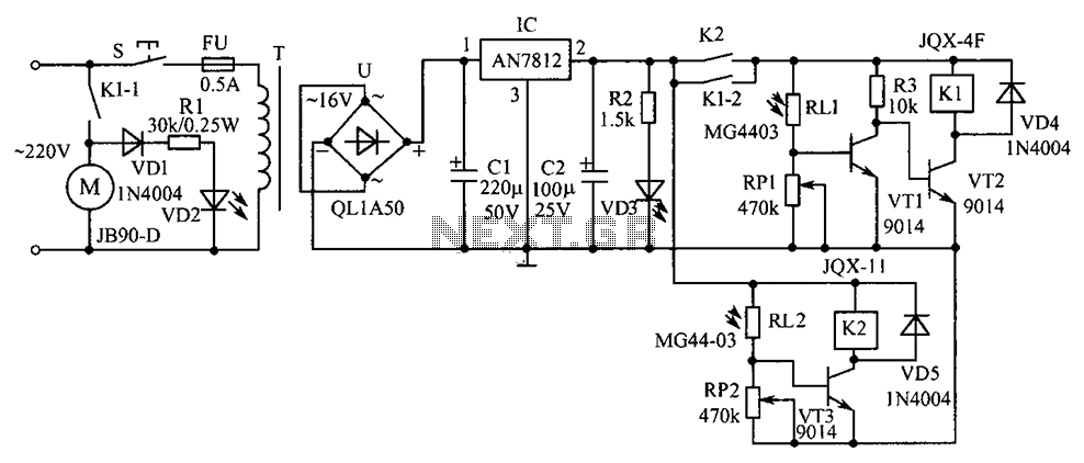
Commonly used in industrial and mining enterprises, a power mixer is employed for mixing materials. Due to the presence of odors or dust, operators should maintain a safe distance from the equipment. The system utilizes light control for operation....
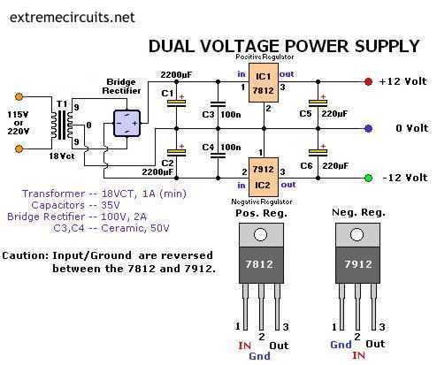
The following circuit diagram of a dual voltage power supply can be used for miscellaneous applications. It requires a few components to build. The most important components of this circuit are regulators: 1: (AN) 7812 and 2: (AN) 7912....
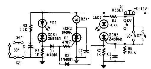
A straightforward high-power alarm driver electronic project can be developed using this circuit diagram. This high-power alarm driver project utilizes a low-power SCR to trigger a high-power SCR. When switches S2, S3, or S4 are opened or switches S5,...
As the demand for VRM output current increases, the components and parts of the SR-Buck converter can no longer meet the requirements for the new generation microprocessors needing 100 A. Additionally, creating filtering inductance for high currents is quite...
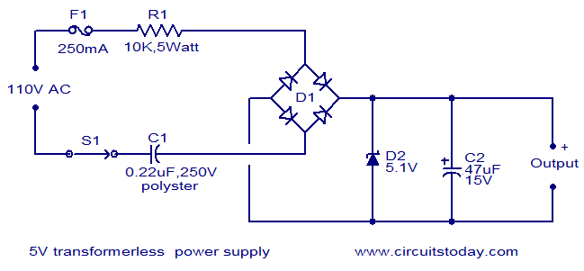
The circuit diagram illustrates a 5V transformerless power supply utilizing minimal components. The operation of this circuit is straightforward. Resistor R1 serves as a current limiter, while bridge D1 rectifies the mains voltage. The Zener diode regulates the output...
This is a high-quality stabilized power supply circuit diagram. The output voltage can be adjusted from 0 volts to 30 volts DC, and the current output value can be adjusted from 0.002 A to 3 A. The circuit begins...