
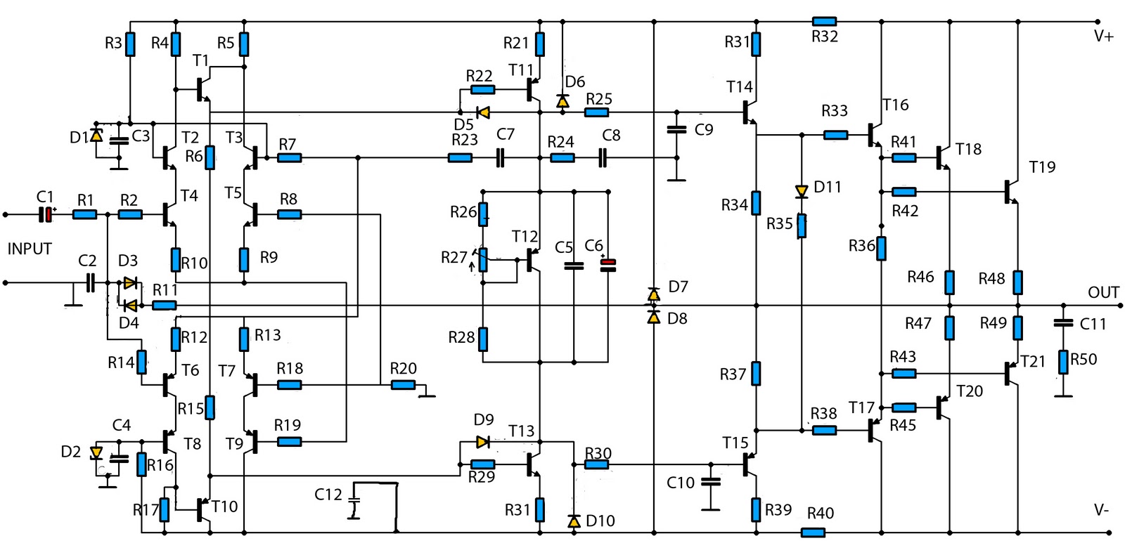
20W Class-A Amplifier
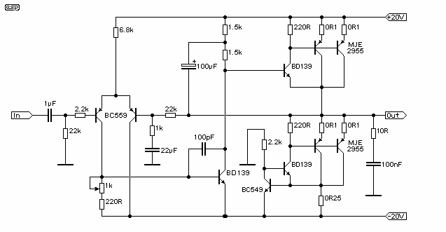
The described amplifier circuit is a Class-A power amplifier capable of delivering 60 watts of output power, which is a common requirement in audio amplification applications. Class-A amplifiers are known for their linearity and low distortion characteristics, making them suitable for high-fidelity audio applications. The design modifications for true Class-A operation typically involve biasing the output transistors to conduct for the entire input signal cycle, thereby minimizing crossover distortion.
The circuit is powered by dual power supplies of +/-20 volts, which can be achieved through various means, including conventional linear power supplies or regulated supplies. The use of a capacitance multiplier can enhance the power supply's performance by reducing ripple and providing a more stable voltage under varying load conditions. This is particularly important in Class-A amplifiers, where the output stage is always conducting, leading to higher power dissipation and potential thermal issues.
The amplifier's basic circuitry likely includes a differential input stage, which amplifies the audio signal while rejecting common-mode noise, followed by a voltage gain stage and a push-pull output stage to drive the load. Feedback mechanisms are essential in this design to maintain stability and linearity, as well as to control gain.
Thermal management is a critical aspect of Class-A amplifier design due to the continuous conduction of output transistors. Adequate heat sinking must be provided to dissipate heat generated during operation, ensuring reliable performance and longevity of the components.
Overall, this amplifier design appears to be well-received by users, with positive reports suggesting that it meets performance expectations as simulated. Further empirical testing will validate the theoretical design, ensuring that it operates effectively in practical applications.This amp uses the basic circuitry of the 60W power amp (see Index), but modified for true Class-A operation - it should be pretty nice! This amp has been built by several readers, and the reports I have received have been very positive. With simulations, everything appears to be as expected, but although I have yet to actually build it and test it out thoroughly, no-one has had any problems so far. Using +/-20 Volt supplies - either conventional, regulated or using a capacitance multipli 🔗 External reference
Related Circuits
This is a Class AB transistor power amplifier. It is straightforward to construct, utilizing standard components, and is known for its stability and reliability. The entire circuit employs commonly available parts and can be easily assembled on a general-purpose...
The third series of the function utilizes the same system, specifically BTL (Bridge Transformer Less). This configuration offers several advantages, including the elimination of coupling capacitors and coupling transformers. The BTL (Bridge Transformer Less) configuration is a significant advancement in...

This car audio amplifier circuit is based on the LA47536 audio amplifier integrated circuit designed by Sanyo. This audio amplifier circuit is specifically designed for car audio power amplifiers. The LA47536 car audio amplifier IC features four output channels...
In a servo system, the current drive connection is frequently utilized. The output current (IOUT) is proportional to the input channel number (y). Using the current drive mode can mitigate issues caused by the motor's large inductance, which induces...
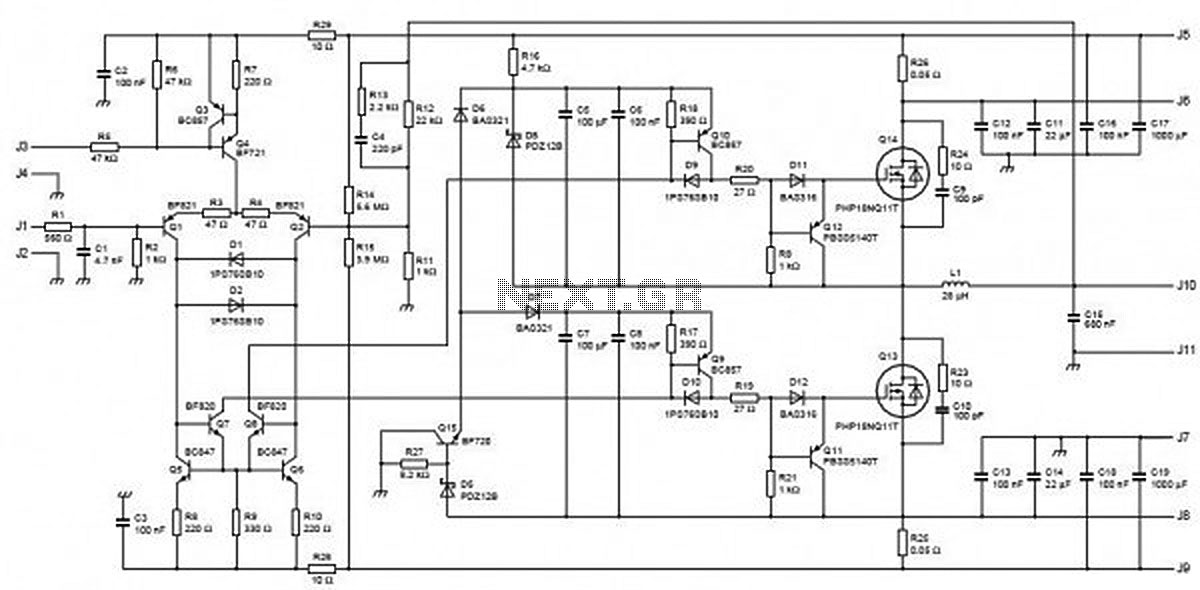
This circuit is capable of delivering approximately 200W of power output, produced by Phillips Semiconductor. It utilizes two PHP1BN11QT devices and operates with an input voltage range of 30 to 45 Volts DC. The described circuit is a high-power switching...
This is a mono amplifier circuit with a high output power of 1400W. It is well-suited for use in large rooms with woofer and full-range speakers, delivering a loud and clear sound with minimal noise. The amplifier utilizes high-quality...