
1400w audio power amplifier

The amplifier circuit described operates as a high-power audio amplifier designed for mono output, making it ideal for large audio setups where significant sound levels are required. The output stage can deliver up to 1400W, which is suitable for driving large woofer speakers and full-range speakers, ensuring that the audio output is both loud and clear, with a focus on maintaining audio fidelity and minimizing distortion.
The circuit employs high-quality transistors that can handle the substantial output power. The choice of transistors in the final amplification stage is flexible, allowing for the use of various high-power models, which can be selected based on availability and performance characteristics. The power supply requirements are critical, with a minimum voltage of ±25V ensuring adequate headroom for operation, while the maximum voltage of ±90V allows for robust performance under high load conditions.
Thermal management is a significant consideration in the design of this amplifier circuit. Transistors 11 to 17, which are integral to the amplification process, must be mounted with heatsinks to dissipate the heat generated during operation effectively. This is crucial to prevent thermal overload and ensure reliable performance. Additionally, the final amplifier transistors, labeled 18 to 21, also require heatsinking to maintain optimal operating temperatures and prevent thermal failure.
In summary, this amplifier circuit is engineered for high output power applications, with careful attention to component selection and thermal management, making it suitable for demanding audio environments. Proper implementation of heatsinks and adherence to power supply specifications will ensure that the amplifier operates efficiently and reliably, delivering high-quality audio performance.This is an amplifier circuit that has a high output power is 1400W mono, the audio amplifier circuit is very suitable when used in a large room, using a woofer speaker, and fullrange. To sound out very nice, loud sound and almost no noise. The amplifier using a transistor amplifier-quality, and for the final amplifier transistors can use a variety
of high-power transistors. Minimum required supply voltage + / - 25V and a maximum of up to + /-90V. For transistor 11 to 17 should use a heatsink, because if the maximum working range of the transistor heat and should be to install the heatsink. But do not forget also to the final amplifier transistor circuit should also be given a heatsink such as transistors 18 to 21.
🔗 External reference
Related Circuits
This audio peak detector enables monitoring of a pair of stereo channels using a single LED indicator. The circuit employs identical configurations for both left and right channels. It utilizes the switching levels of Schmitt trigger NAND gates within...
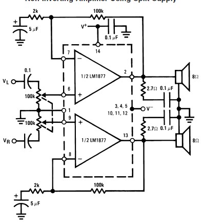
This audio amplifier circuit is designed to deliver 2W per channel continuously into 8-ohm loads. The LM1877 is engineered to function with a minimal number of external components while still offering flexibility for applications in stereo phonographs, tape recorders,...
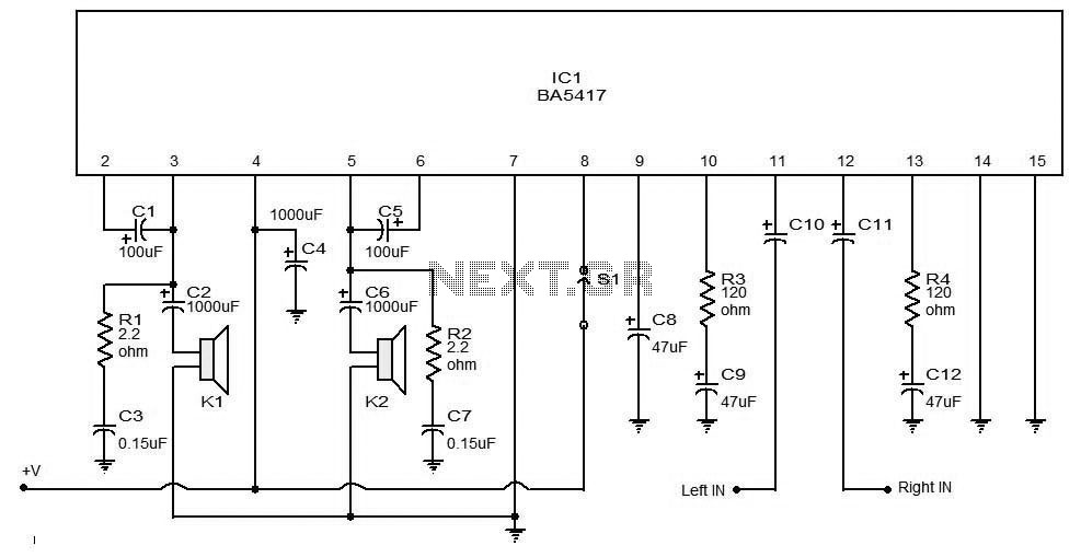
The BA5406 is a dual OTL (output transformerless) monolithic power integrated circuit (IC) featuring two high-output speaker amplifier circuits. It operates effectively with a supply voltage (Vcc) of 12 V and a load resistance (Rl) of 3 Ohms. At...
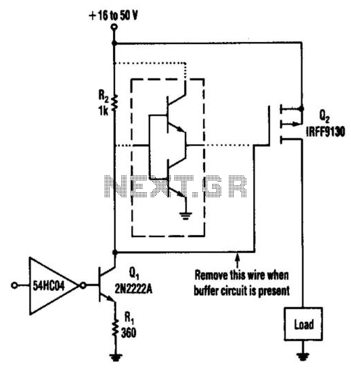
This circuit operates from a 16- to 50-V supply. Adding the buffer circuit (within the dashed lines) offers 100-ns switching times. Otherwise, the circuit switches in 1 µs. Q1 and R1 form a switched current source of about 12...
This is a current sensing circuit that measures the current on the high side, positioned between the load and the positive supply. This circuit takes advantage of... A current sensing circuit serves a crucial role in monitoring the flow of...
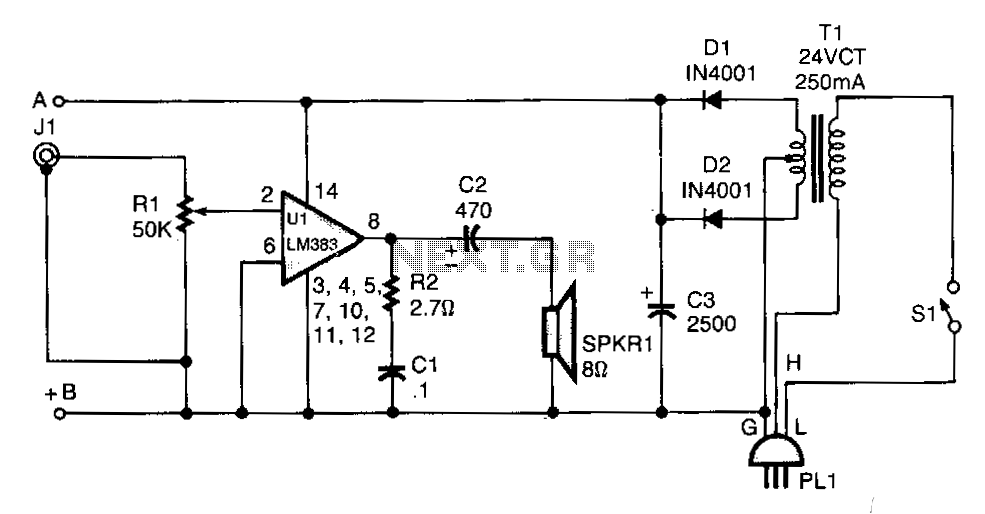
T1 isolates the unit from the line and has a 24-V, center-tapped secondary. The output of the transformer is rectified by diodes D1 and D2 and filtered by capacitor C3 to provide 15 to 18 Vdc. The LM383 has...