
211 SET 40W output design and mfg

This amplifier design harnesses the characteristics of high-power vacuum tubes, specifically the 211 and 845, which are renowned for their warm sound and high fidelity. Operating in Class A2 allows for a linear amplification of the audio signal, ensuring minimal distortion and a rich tonal quality. The choice of a good driver stage is critical; it must be capable of delivering the necessary voltage and current to the output stage while maintaining signal integrity.
The use of a follower stage is essential for impedance matching and signal buffering. A 6BQ5 tube is a traditional choice for this application, providing sufficient gain and drive capability. However, the use of a MOSFET in this role can offer advantages such as lower output impedance, greater thermal stability, and improved linearity. This allows for a more efficient transfer of power to the output stage.
The load impedance is also a crucial factor in the amplifier's performance. A 7K ohm load at 1000 volts is a standard configuration that provides a good balance between power output and efficiency. In contrast, the design incorporating a 10K ohm load at 1100 volts may enhance the overall headroom and dynamic range of the amplifier, allowing it to handle transient signals more effectively.
Simulation tools like Tubecad SE amp CAD are invaluable for analyzing the amplifier's performance characteristics before physical implementation. These simulations can predict the output power, distortion levels, and frequency response, ensuring that the design meets the desired specifications.
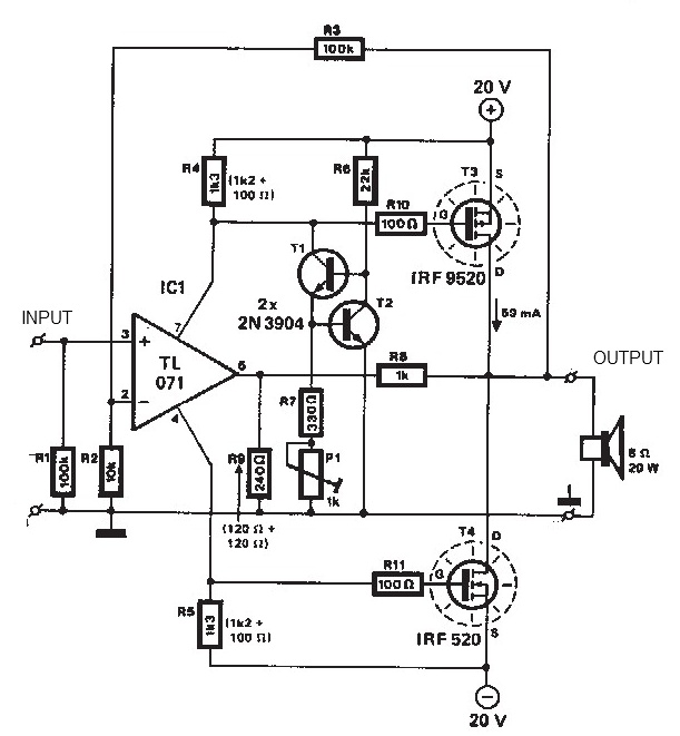
Overall, this amplifier configuration is anticipated to deliver robust performance, making it suitable for audiophiles seeking high-quality sound reproduction. The combination of careful component selection, optimal circuit design, and thorough simulation underpins the expected success of this audio amplifier project.An amp that uses 211 or 845. It puts out just over 40 watts. The tube must run in A2 to get this power, which is not a problem with a good driver. The secret is a good follower, you use a 6BQ5, I use a mosfet. You use 7K ohm load on 1000 volts, I use 10K ohm on 1100 volts. Both simulate to about 40 watts using Tubecad SE amp cad. It should work very well and sound nice. 🔗 External reference
Related Circuits
The circuit was designed to create an electronic siren to produce an alert sound in emergency situations or any circumstances that require its usage. The 4011 is a quad 2-input NAND gate integrated circuit, characterized by minimal voltage supply...
The audio amplifier illustrated in this circuit diagram is a straightforward and efficient audio amplifier circuit based on the TDA1308 integrated class-AB stereo headphone amplifier. This device is manufactured using a 1 mm Complementary Metal Oxide Semiconductor (CMOS) process...
An oscillator circuit is an electronic circuit that produces a periodic signal. The term quadrature refers to a fourth (1/4) phase shift of a full wave cycle (1/4 of... An oscillator circuit is a fundamental component in various electronic systems,...
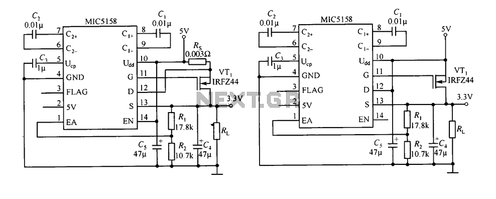
The circuit consists of peripheral components for the MIC5158, a linear regulator that converts a 5V input into a 3.3V output with a maximum current of 10A. When the input voltage (Ui) is 5V, an N-channel MOSFET, specifically the...
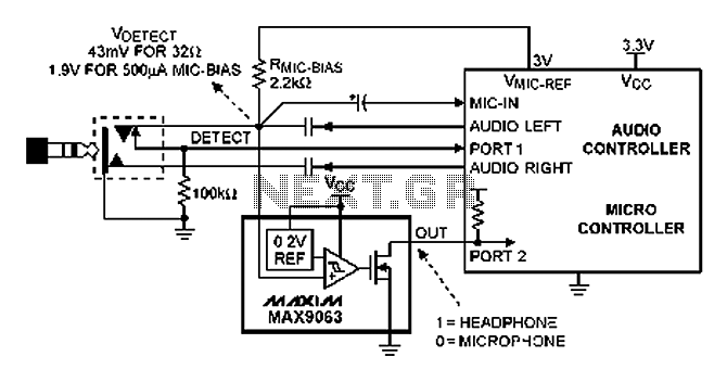
A headphone type detection circuit is illustrated in the attached figure. The 2.2k RMIC-BIAS resistor connected to the audio controller provides a low-noise reference voltage (VMIC-REF). When the audio jack is inserted, the VMIC-REF voltage through RMIC-BIAS is applied...
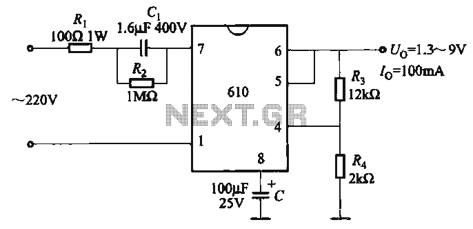
The output voltage can be calculated as follows: U = 1.3 (1 + R3 / R4) (V), where R3 and R4 are part of an adjustment potentiometer, allowing for a continuously adjustable output voltage. The described circuit involves a voltage...