
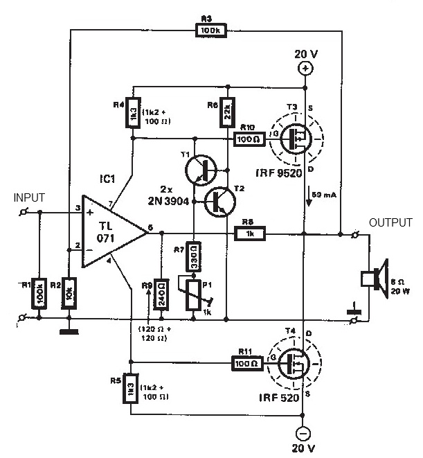
Mosfet Amplifier 20Watt Output Power Schematic Diagram
The TDA1308 and TDA1308A are integrated circuits specifically designed for audio amplification, making them suitable for portable devices such as MP3 players, portable speakers, and other battery-operated audio equipment. The class-AB configuration provides a good balance between efficiency and audio quality, allowing for minimal distortion while delivering sufficient power output for driving headphones or small speakers.
The circuit typically includes input capacitors to block any DC offset from the audio source and coupling capacitors at the output to prevent DC from reaching the load. Feedback resistors are employed to set the gain of the amplifier, allowing users to adjust the output level according to their requirements. Additionally, bypass capacitors are often included near the power supply pins of the TDA1308 or TDA1308A to ensure stable operation and reduce noise.
For optimal performance, it is crucial to adhere to the recommended power supply specifications. The use of a regulated power supply is advised to maintain a consistent voltage level, which is essential for achieving the desired output power and audio clarity. Furthermore, thermal management should be considered, especially in compact designs, to prevent overheating during prolonged operation.
Overall, this audio amplifier circuit is a practical solution for enhancing audio output in portable applications, offering versatility and efficiency in a compact form factor.This audio amplifier showed in this circuit diagram, is a very simple and efficiency audio amplifier circuit based on the TDA1308 integrated class-AB stereo headphone. The device is fabricated in a 1 mm Complementary Metal Oxide Semiconductor (CMOS) process and has been primarily developed for portable digital audio applications.
You can use thi s circuit diagram with TDA1308 or TDA1308A, the difference between the TDA1308 and the TDA1308A is that the TDA1308A can be used at low supply voltages. The maximum output power that can be obtained with this circuit is around 80mwatts. This audio amplifier circuit requires a very low voltage power supply : from 3 to 7 volts for single supply or 1.
5 to 3 volts for dual supply, for TDA1308. The TDA1308A supports a low voltage input down to 1. 2 volts, but the typical power supply required for both circuits is 5 volts for single supply and 2. 5 volts for dual supply. You are reading the Circuits of Mosfet Amplifier 20Watt Output Power And this circuit permalink url it is 🔗 External reference
Related Circuits
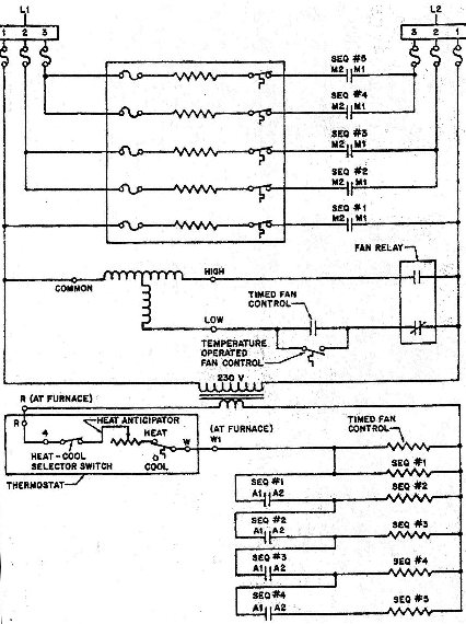
This diagram allows for easy identification of test points related to Applied Voltage and Potential Voltage. For instance, by isolating one of the heating elements, an N.O. (Normally Open) switch can be observed wired in series with it. The...
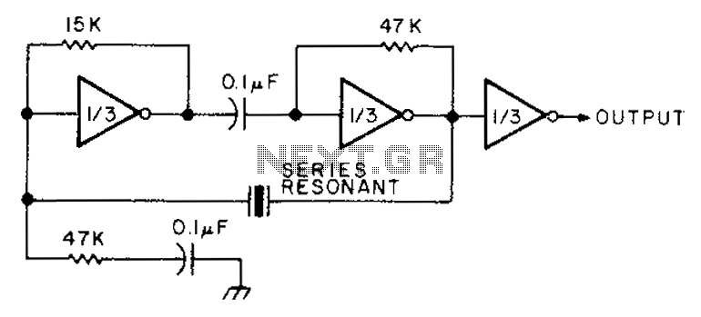
The circuit diagram illustrates the connection of all three components of the series resonant crystal and triple CD4049 inverter. The supply voltage range is between 3 to 15 volts, making it suitable for various applications. This design is compact...
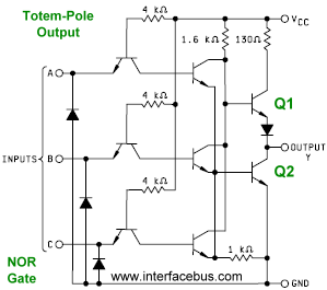
A type of output structure used with integrated circuits in which one transistor drives the output high while another transistor connected below it pulls the output low. Many integrated circuits utilize Totem-Pole Outputs; in fact, it is so common...
A unit that is often very useful for isolating two stages in sound circuits. This circuit incorporates an amplification unit with a gain of X1. It employs only local negative feedback rather than total negative feedback, resulting in very...
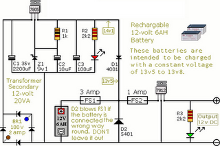
The following circuit illustrates an Alarm Power Supply Circuit Diagram. Features include a 1-amp current output, suitable for a Modular Burglar Alarm operating at 12 volts. The Alarm Power Supply Circuit is designed to provide a stable and reliable power...
This headphone buffer is based on Greg Szekeres' MOSFET Headphone Driver. It is a robust and reliable zero feedback, class A circuit. The power supply is choke regulated. The circuit is configured for low impedance headphones like my 32-ohm...
Warning: include(partials/cookie-banner.php): Failed to open stream: Permission denied in /var/www/html/nextgr/view-circuit.php on line 713
Warning: include(): Failed opening 'partials/cookie-banner.php' for inclusion (include_path='.:/usr/share/php') in /var/www/html/nextgr/view-circuit.php on line 713