
Adjustable output voltage power supply circuit MAX610
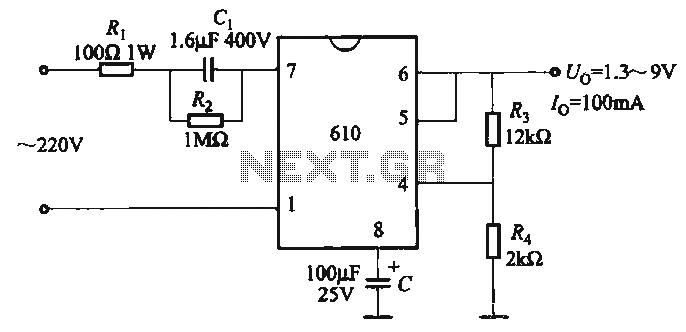
The described circuit involves a voltage output that is dependent on the resistors R3 and R4, which form a voltage divider configuration in conjunction with a potentiometer. The formula indicates that the output voltage (U) is 1.3 times the sum of 1 and the ratio of R3 to R4. This implies that by varying the resistance values of R3 and R4, the output voltage can be finely tuned to meet specific requirements.
In practical applications, the potentiometer serves as a means to adjust the resistance values dynamically. When R3 is increased relative to R4, the output voltage increases, whereas decreasing R3 or increasing R4 will lower the output voltage. This circuit can be utilized in various applications where precise voltage control is necessary, such as in power supplies, signal conditioning, or sensor interfaces.
The stability of the output voltage can be influenced by the tolerance of the resistors used, as well as the quality of the potentiometer. It is essential to select components that can withstand the operational conditions to ensure reliable performance. Additionally, the circuit may include filtering capacitors to stabilize the output and minimize voltage ripple, particularly in applications that require smooth and consistent voltage levels. Proper layout and grounding techniques should also be employed to reduce noise and interference in the circuit.The output voltage can be calculated as follows: U. . = 1. 3 (1 + R3 / R4) (V) adjustment potentiometer , continuously adjustable output voltage.
Related Circuits

The servo motor is a type of traditional motor that serves as the execution component in automated devices. Its most significant characteristic is its controllability; when a control signal is applied, the servo motor rotates, with its speed being...
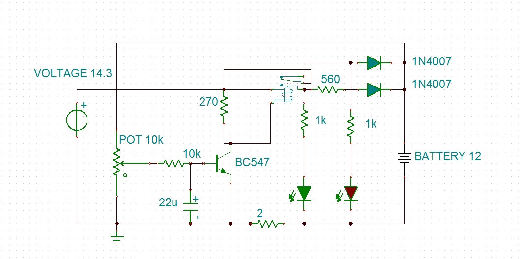
Using a transistor will not yield accurate results, and the adjustment process can become quite tedious. The circuit is technically correct; if the tripping point can be adjusted properly, it may function as intended. Vinod states that he created...
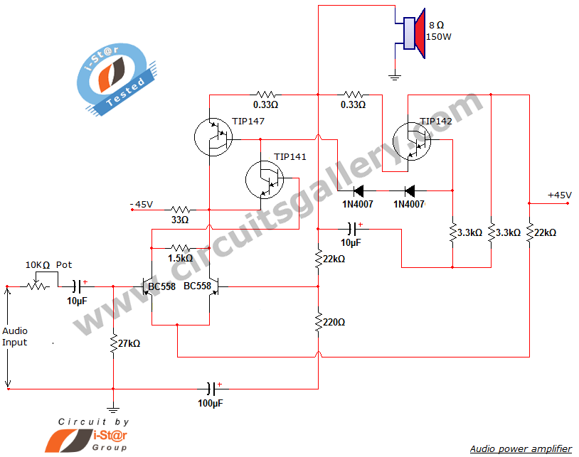
This document presents a new audio power amplifier schematic utilizing TIP darlington pair transistors. It is suitable for both home audio and car audio amplifiers. The TIP142 and TIP147 darlington pair transistors create a push-pull high-power amplifier configuration, while...
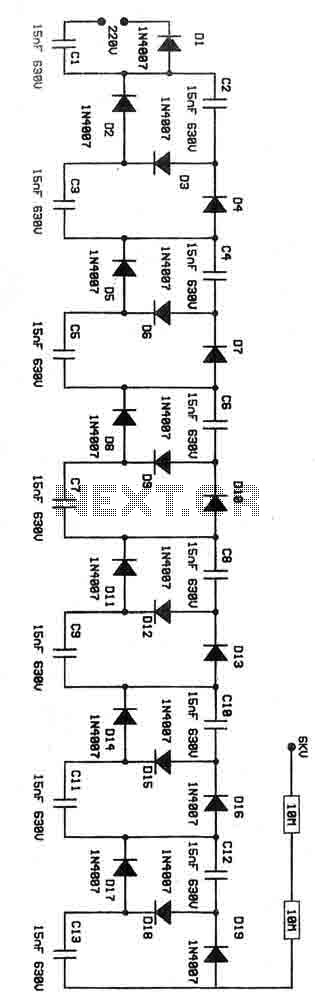
This is a voltage multiplier circuit functioning as an ionizer. It is designed to convert 220V from the mains supply into an output of approximately 6kV. Caution is advised when handling this circuit due to the potential dangers associated...
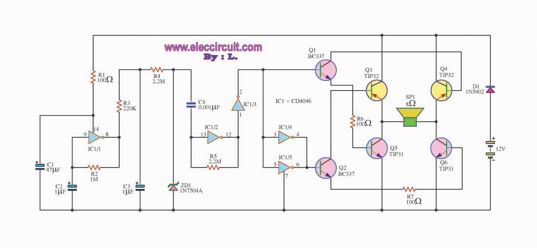
This is a simple siren sound generator with high power output and significant noise levels. The circuit utilizes digital integrated circuits (ICs), specifically the CD4046, in an inverter configuration along with four transistors to increase the current output to...
There have been several requests for a quiz circuit, leading to the development of a four-input design that can be easily modified. This design utilizes four integrated circuits (ICs) and features four input circuits, four independent outputs, and a...