
220V 200W Bulb flasher
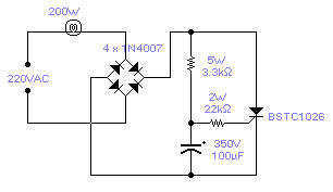
This circuit is designed as a simple power flasher, suitable for applications where a flashing light is required without the need for complex circuitry. The primary component of this circuit is a Silicon Controlled Rectifier (SCR), which serves as a switch to control the power delivered to the load—typically a 100W incandescent bulb. The circuit operates at a frequency of approximately 1Hz, creating a flashing effect with a 50% duty cycle, meaning the light is on for half the duration of each cycle.
The maximum load capacity of this circuit is 200W, allowing for the use of higher wattage bulbs if necessary. However, it is essential to note that the frequency of the flashing can be adjusted by changing the capacitance value of the capacitor in the circuit. Increasing the capacitance will lower the frequency, while decreasing it will raise the frequency, thus providing flexibility in the design.
While the circuit has not been tested at 110VAC, it is anticipated that it would function correctly with appropriate adjustments to the resistor values—specifically, reducing them to about half of their stated values to accommodate the lower voltage. The SCR used in this design is from Siemens but can be replaced with any equivalent semiconductor that has standard gate sensitivity characteristics.
Safety precautions are critical when working with circuits connected directly to the mains. It is imperative to ensure that all components are rated for the voltage and current they will encounter in operation. A more modern iteration of this circuit might incorporate a sensitive gate SCR for improved performance, along with low power resistors and a 10µF, 250V electrolytic capacitor, which would enhance reliability and efficiency while maintaining the desired functionality. Proper isolation and protective measures should always be employed to mitigate risks associated with high voltage operation.There is no need to resort to complex circuitry if what you are looking for is a simple power flasher. The light will flash at around 1Hz with a 100W bulb at a duty cycle of 50%. The max. load that can be driven with this circuit is 200W and if you wish to have a different frequency you have to change the value of the capacitor.
Operation at 110VAC has not been tested although I expect it to work provided the resistors are set at about half the stated value. The SCR is manufactured by Siemens but any other equivalent semiconductor, with standard gate sensitivity, should work fine.
WARNING! - This circuit is directly connected to the mains and proper safety precautions should be taken. A more modern design would use a sensitive gate SCR, other low power resistors and a 10?F, 250V electrolytic capacitor. 🔗 External reference
Related Circuits
Using this circuit you can convert the 12V dc into the 220V Ac. In this circuit, 4047 is used to generate the square wave of 50Hz and amplify the current and then amplify the voltage by using the step...
This project flashes eight LEDs in a seemingly random manner. It utilizes a 4026 combined counter and display driver integrated circuit (IC) designed for driving 7-segment LED displays. The sequence is not entirely random, as seven of the LEDs...
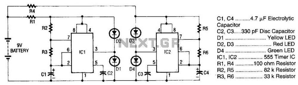
The super LED flasher consists of two complete LED flasher circuits integrated onto a single circuit board. The first LED flasher is comprised of IC1 and LEDs D1 and D2. IC1 is a 555 timer IC configured as an...
Output transformer core sourced from a flea market, light blue in color, marked as A-438281-2-9H9-3, with an outer diameter of 47 mm, an inner diameter of 24 mm, and a height of 13 mm. No data is available regarding...
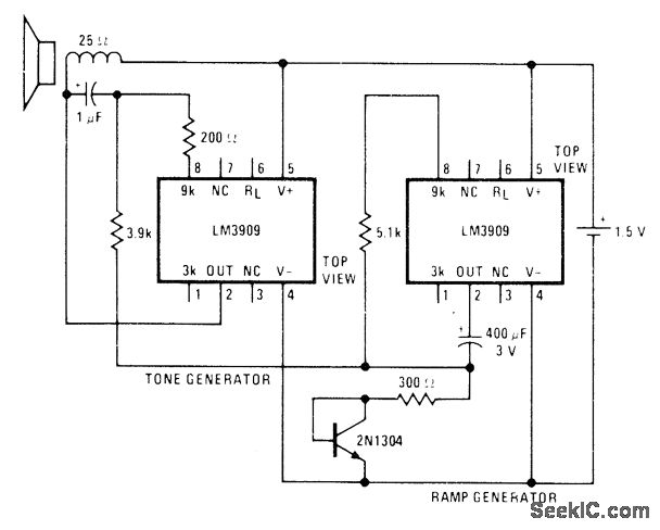
A low-drain circuit powered by a 1.5-V cell utilizes National LM3909 flasher integrated circuits (ICs) to replicate the "whooper" sounds characteristic of electronic sirens found in some city police cars and ambulances. Two flashers are necessary to create the...
Inverters IC1-a and IC1-b form a multivibrator, while IC1-c acts as a buffer. Inverter IC1-d is configured such that its output is the inverse of IC1-c; when pin 6 is high, pin 8 is low, and vice versa. As...