
Super Led Flasher Circuit
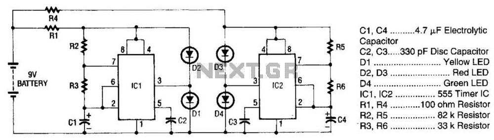
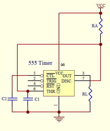
The super LED flasher circuit utilizes two 555 timer ICs, each configured as an astable multivibrator to create a flashing effect with two pairs of LEDs. The first section of the circuit, featuring IC1, is responsible for controlling the flashing of LEDs D1 and D2. The frequency of oscillation is determined by the values of resistors R2 and R3 along with capacitor C1. The timing components are selected based on the desired frequency of the LED flashing; for instance, a higher resistance value or capacitance will result in a slower flashing rate.
Resistor R1 is crucial for protecting the 555 timer from excessive voltage, ensuring that the IC operates within its specified limits. The output from pin 3 of IC1 is connected to the anode of LED D1, while the cathode is connected to ground. Similarly, LED D2 is connected to the output in a reverse manner, allowing it to light up when the output is low. The polarity-sensitive nature of the LEDs ensures that only one LED is illuminated at any given time, creating a visually appealing flashing effect.
The second LED flasher circuit, which consists of IC2, LEDs D3 and D4, mirrors the design of the first circuit. The same principles apply, with IC2 generating a complementary flashing effect for the second pair of LEDs. The design allows for simultaneous operation of both circuits, resulting in a coordinated flashing pattern. The integration of both circuits on a single board optimizes space and simplifies the overall design, making it suitable for various applications where visual alerts or indicators are necessary.
This dual LED flasher setup can be employed in decorative lighting, alarms, or any application requiring visual signaling. The flexibility of the 555 timer IC allows for easy adjustments to the flashing frequency, making it adaptable to different user requirements. The super LED flasher is actually two complete LED flasher circuits on one circuit board. The first, LED flasher is made up of 1C1 and LEDs D1 and D2. IC1 is a 555 timer IC configured as an astable (free-running) multivibrator with its output on pin 3. The frequency of the 555`s oscillation is controlled by R2, R3, and CI. Resistor R1 limits the input voltage to a low enough level to prevent damage to the IC. As the 555 IC oscillates, the output of pin 3 goes high (+) then low (-). When the output is high it supplies current to Dl, which lights up. When it is low, pin 3 sinks current and D2 lights up. This happens because LEDs are polarity-sensi-tive (like all other diodes, they permit current flow in only one direction) and one lead of each LED has been connected to the respective polarity needed to light that LED.
The second LED llasher, made up of IC2 and LEDs D3 and D4, operates in the same way as the first LED flasher. 🔗 External reference
Related Circuits

A simple audio watt meter circuit or an audio power or audio level meter circuit with diagram and schematics to measure amplifier audio output power in watts. The audio watt meter circuit is designed to measure the output power of...
This Intercom is powered by two 9-volt batteries and uses only current when the Intercom is used. Both units are connected via a two-wire little cable or simply two wires (dotted lines). The loudspeakers act both as loudspeakers and...
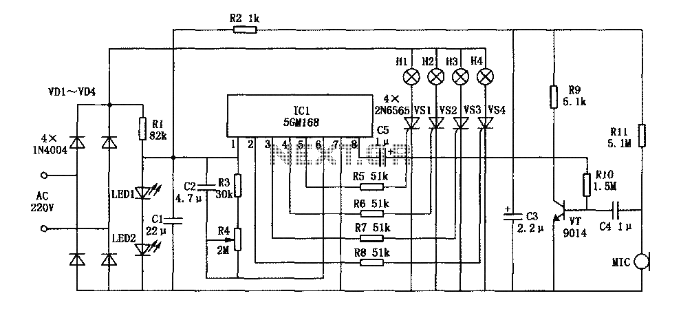
This document describes a family karaoke lighting design that employs various methods to control the circuit. The control circuit presented here features a four-way light output with loop jumping and speed control capabilities. The practical circuit utilizes a microphone...
This project is provided as a prototyping project as no PC board has been produced. The photographs show the project built on a matrix board using surface-mount components and very fine wire. The final design will require a double-sided...
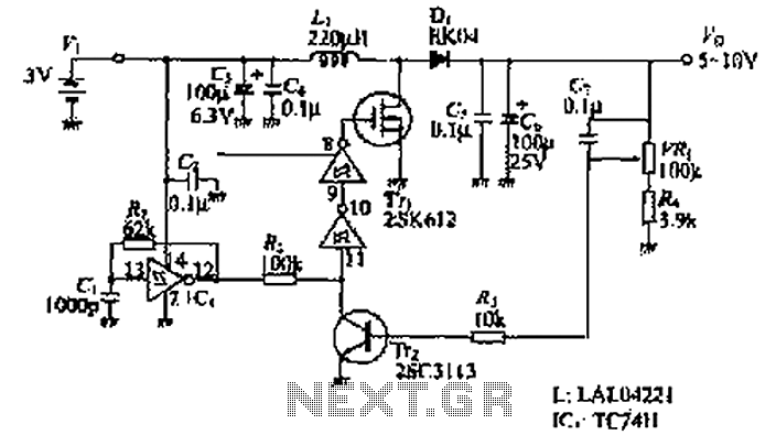
The design of the power supply circuit diagram utilizes an oscillator circuit from the 74HC series of CMOS logic circuits, with a MOSFET as the switching device. This configuration allows for the development of small-scale power supplies suitable for...
The timer circuit is utilized in various projects and is primarily categorized into two types. The first type is an analog RC circuit, where the charging of the capacitor determines the timing of the circuit. This type has a...
Warning: include(partials/cookie-banner.php): Failed to open stream: Permission denied in /var/www/html/nextgr/view-circuit.php on line 713
Warning: include(): Failed opening 'partials/cookie-banner.php' for inclusion (include_path='.:/usr/share/php') in /var/www/html/nextgr/view-circuit.php on line 713