
220V AC powered LED lamp drive circuit diagram
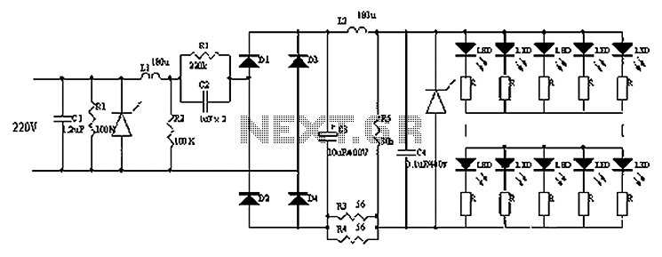
The described circuit comprises multiple components that work together to ensure power stability and protection for sensitive electronic devices, particularly LEDs. The primary power supply serves as the initial stage, providing the necessary voltage and current to the circuit. The inclusion of capacitors C1, C2, C3, and C4 plays a critical role in filtering and smoothing the output voltage. Capacitor C1, in conjunction with resistor R1, forms a low-pass filter that mitigates high-frequency noise, while C2 and R2 further enhance the filtering process.
The varistor is a vital component in this design, as it provides overvoltage protection by clamping voltage spikes that may occur due to transient surges. When the voltage exceeds a predefined threshold, the varistor conducts, diverting excess energy away from the LEDs and preventing potential damage. This is particularly important in applications where voltage transients are common.
Inductor L1 is included in the circuit to improve filtering efficiency; it works in tandem with the capacitors to create a more stable DC output. The inductance helps to smooth out current fluctuations, ensuring a more consistent power supply to the load. Additionally, inductor L2 may be employed in conjunction with the other components to further enhance the filtering capabilities of the circuit.
In summary, this circuit design effectively utilizes a combination of capacitors, resistors, inductors, and a varistor to create a robust filtering solution that protects LED components from high-voltage transients while ensuring a stable power supply. The use of a double-smoothing circuit enhances the overall performance, making it suitable for applications that require reliable operation under varying electrical conditions. Circuits, C1, R1, varistors, L1, R2 filter circuit composed of a primary power supply, can filter out transient overvoltage input, C2, R2 down circuit composed, C3, C4, L2, and varistor composition rectified filter circuit. This circuit uses a double-smoothing circuit, can effectively protect the LED breakdown is not damaged high-voltage transient.
Related Circuits
This circuit allows for the adjustment of resistance using a potentiometer and the adjustment of capacitance by opening or closing switches. By manipulating the configuration of these switches, various combinations can be achieved to obtain different effective capacitance values....
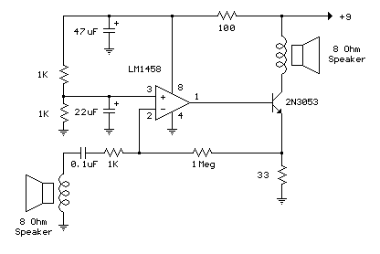
The example below illustrates the use of an operational amplifier (op-amp) as an audio amplifier in a basic intercom system. A small 8-ohm speaker is utilized as a microphone, which is connected to the op-amp input through a 0.1...
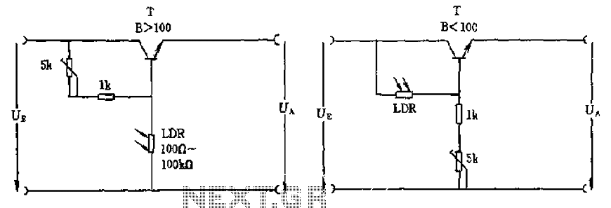
The circuit depicted involves a photoresistor (LDR) connected to a transistor, which operates at either a high or low level based on light conditions. The amplification factor of the transistor is 100, which is adequate for the application. The...
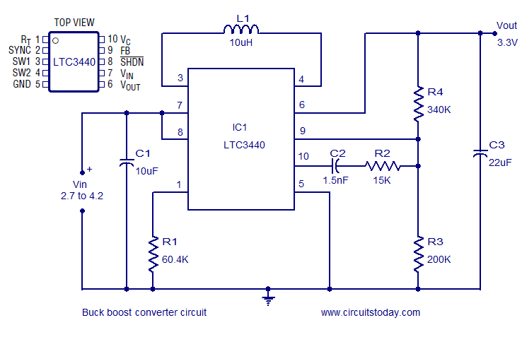
A highly efficient buck-boost converter circuit is presented, utilizing the LTC3440 buck-boost regulator IC from Linear Technology. This IC requires only one inductor and achieves efficiency levels of up to 96%. For applications where the output voltage is below...
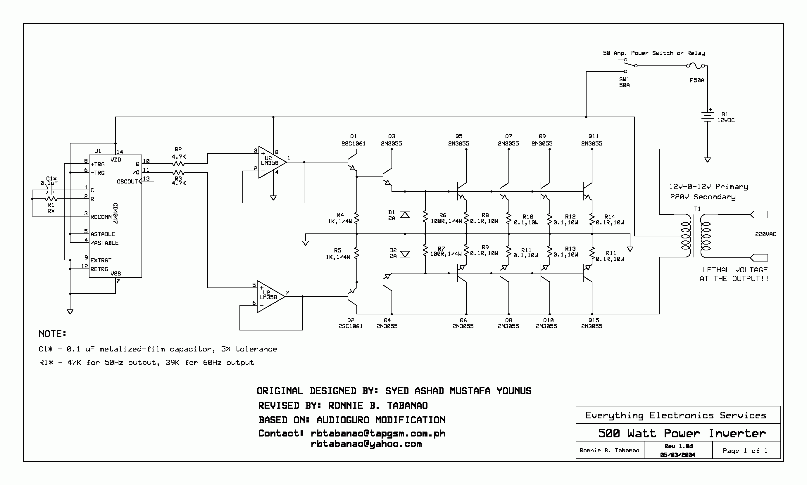
Using this circuit you can convert the 12V dc into the 220V AC. In this circuit, 4047 is used to generate the square wave of 50Hz and amplify the current and then amplify the voltage by using the step...
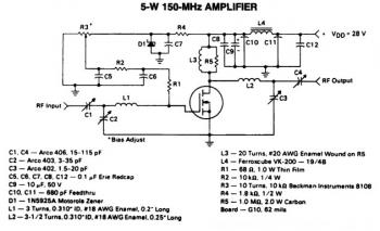
This is a 5W -150MHz RF amplifier circuit that utilizes the MRF123 TMOSFET. The MRF123 is a high-gain FET which may exhibit instability at both VHF and UHF frequencies; therefore, a 68 Ohm input loading resistor is employed to...
Warning: include(partials/cookie-banner.php): Failed to open stream: Permission denied in /var/www/html/nextgr/view-circuit.php on line 713
Warning: include(): Failed opening 'partials/cookie-banner.php' for inclusion (include_path='.:/usr/share/php') in /var/www/html/nextgr/view-circuit.php on line 713