
Photoresistor LDR light control switch circuit diagram
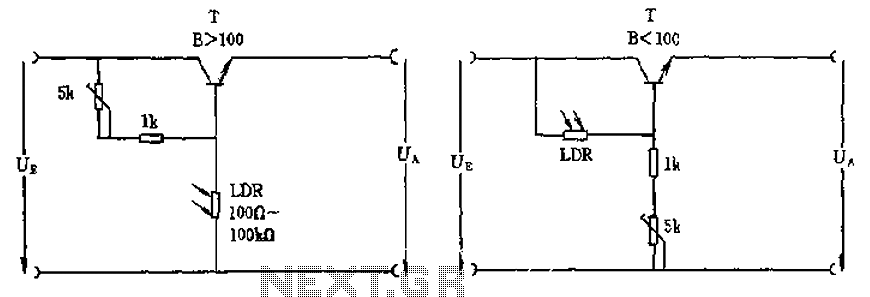
The circuit utilizes a photoresistor (Light Dependent Resistor, LDR) as the primary sensor for detecting ambient light levels. The LDR exhibits a significant change in resistance based on the intensity of light falling on it; typically, its resistance decreases in bright light and increases in darkness. This property is crucial for the operation of the circuit, as it determines the behavior of the connected transistor.
In this configuration, the LDR is connected to the base of a standard bipolar junction transistor (BJT) with a gain factor (h_FE) of approximately 100. This transistor acts as a switch or amplifier, enabling the control of output signals based on the input from the LDR. When the LDR is exposed to light, its resistance drops, allowing current to flow into the base of the transistor, which in turn allows a larger current to flow from the collector to the emitter, effectively turning the transistor "on." Conversely, in low light conditions, the resistance of the LDR increases, reducing the base current and turning the transistor "off."
For applications requiring the control of higher power loads, such as motors or lamps, it is advisable to employ a Darlington pair configuration. A Darlington transistor consists of two BJTs connected in such a way that the current amplified by the first transistor is further amplified by the second. This configuration provides a much higher current gain, making it suitable for switching larger loads without requiring significant input current, thus enhancing the circuit's efficiency and reliability.
In summary, the circuit effectively utilizes an LDR to control a transistor's state based on light intensity, with the option to scale the design for higher power applications through the use of Darlington transistors, ensuring versatility and adaptability in various electronic applications. As shown in the circuit, there is the incident at the time, this circuit is connected with photoresistor LDR transistor is turned high or zero level. Amplification factor of tr ansistor B 100 is sufficient, the photosensitive resistor between 100 ~ 100k Europe, corresponding to the case when the light irradiation and dark. If you want to control high power loads should be used Darlington transistors.
Related Circuits
Often, for various reasons, individuals forget or are unable to water the plants in their homes. Many humidity sensor units merely alert users with a beeping sound or a flashing light when the pot requires watering. However, what if...
Some resistors on the circuit board of a Roland KC-300 amplifier have burned out and are so charred that their specifications cannot be determined. The resistors in question are R82, R83, R85, R92, and R93. Resistors R92 and R93...
This strobe light operates from standard 120-Vac power. Resistor R1 limits the amount of current applied to the voltage doubler stage, which consists of capacitors C1, C2, C3, and diodes D1, D2, along with capacitors C4, C5, and C6....
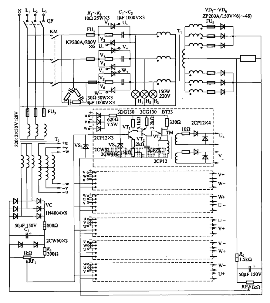
A three-phase thyristor power regulator circuit designed for plating applications, capable of handling currents from 1200A to 6000A at a voltage of 10V. The circuit comprises a main circuit, a trigger circuit, synchronous power components, and a voltage negative...
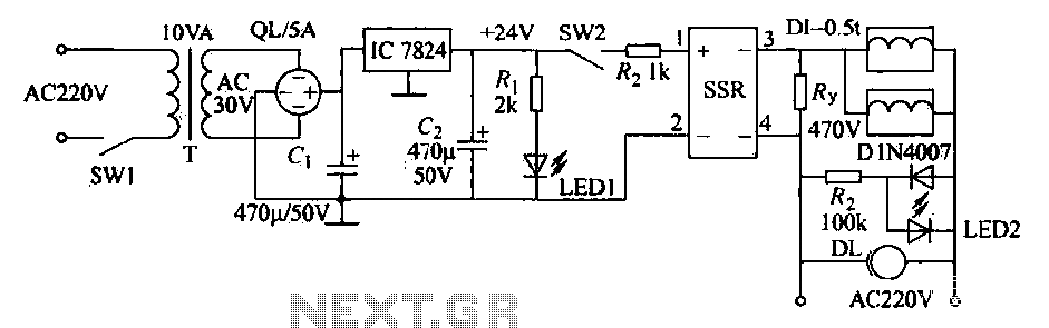
An AC solenoid-driven control circuit utilizing the SSR principle is illustrated. When switch SW1 is closed, a 220V AC transformer steps down the voltage to 30V AC through transformer T. The circuit includes a rectifier, capacitor C, and a...
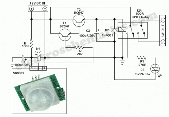
The SB0061 is a pyroelectric sensor module designed for human body detection. It integrates a PIR (Passive Infrared) detector with a Fresnel lens on a compact printed circuit board (PCB), along with an analog integrated circuit (IC) identified as...