
Buck boost converter circuit
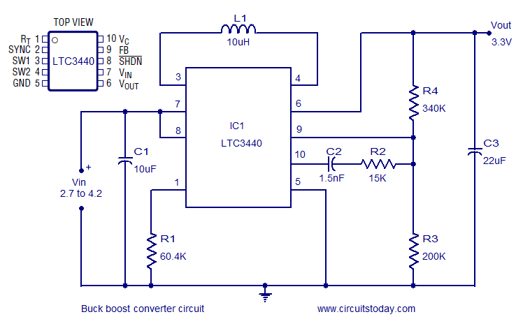
The LTC3440 buck-boost converter circuit is designed for applications requiring efficient voltage regulation across a wide input voltage range. The circuit's architecture allows it to step up or step down the input voltage to maintain a consistent output of 3.3V, which is suitable for powering various electronic devices. The use of a single inductor simplifies the design and reduces component count, which can be beneficial for space-constrained applications.
The oscillator frequency, determined by resistor R1, plays a critical role in the performance of the converter. A higher frequency can lead to smaller inductor and capacitor sizes, improving the overall compactness of the circuit. However, it is essential to balance frequency and efficiency, as higher frequencies may introduce increased switching losses.
The input bypass capacitor, C1, is crucial for maintaining stable operation by filtering out high-frequency noise that may be present on the input voltage line. This helps to ensure that the LTC3440 operates within its specified parameters and enhances the reliability of the output voltage.
The output filter capacitor, C3, smooths out the voltage ripple at the output, ensuring a clean and stable 3.3V supply for the load. The output voltage setting resistors (R4) form a voltage divider that allows for precise adjustment of the output voltage level, enabling flexibility in the design for various load requirements.
The frequency compensation network, consisting of C2 and R2, is vital for maintaining stability in the feedback loop of the converter. Proper compensation ensures that the converter responds adequately to changes in load and input voltage without oscillating or becoming unstable.
This buck-boost converter circuit is ideal for battery-powered applications, portable devices, or any system where input voltage may vary widely, providing a reliable and efficient solution for voltage regulation.A very efficient buck boost converter circuit is shown here. The circuit is based on the LTC3440 buck boost regulator IC from Linear Technology. The LTC3440 requires only one inductor and provides up to 96% efficiency. There is no need of Schottky diode for applications where output voltage is less than 4. 3V and the IC can deliver up to 600mA outp ut current. In the circuit the IC is wired as a buck boost regulator providing 3. 3V output from a 2. 7 to 4. 2V input. R1 is the timing resistor which determines the oscillator frequency and it can be varied between 300 KHz to 2MHz by varying the value of R1. C1 is the input bypass capacitor for reducing noise and C3 is the output filter capacitor. Resistors R4, R4 sets the output voltage and the network consisting of C2 and R2 is meant for frequency compensation.
We aim to transmit more information by carrying articles. Please send us an E-mail to wanghuali@hqew. net within 15 days if we are involved in the problems of article content, copyright or other problems. We will delete it soon. 🔗 External reference
Related Circuits
This sound frequency meter circuit is simple to build and can be constructed in a portable format. It can measure frequencies with a minimum level of 10 mV. The sound frequency meter circuit is designed to provide an effective and...
Nowadays, an increasing number of audio-visual devices in homes are interconnected. This is particularly true for televisions, which may be linked to DVD players. In modern home entertainment systems, the integration of various audio-visual devices enhances user experience and convenience....
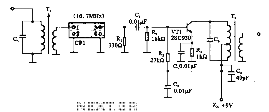
This circuit features a ceramic filter integrated with an FM intermediate frequency (IF) amplifier. The FM IF amplifier circuit primarily consists of an input variable voltage regulator (T), ceramic filters (CF1), and additional components such as the IF amplifier...
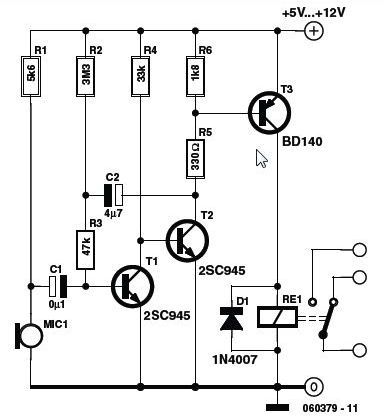
This circuit features a simple, highly sensitive capacitive ON/OFF switch pad that changes the state of a latch and activates an LED without requiring physical contact. The pad can be insulated, and a range of 12mm is easily achievable...
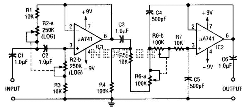
This circuit is a variable audio bandpass filter that features a low cutoff adjustable from approximately 25 Hz to 700 Hz and a high cutoff adjustable from 2.5 kHz to over 20 kHz. The roll-off is set at 12...
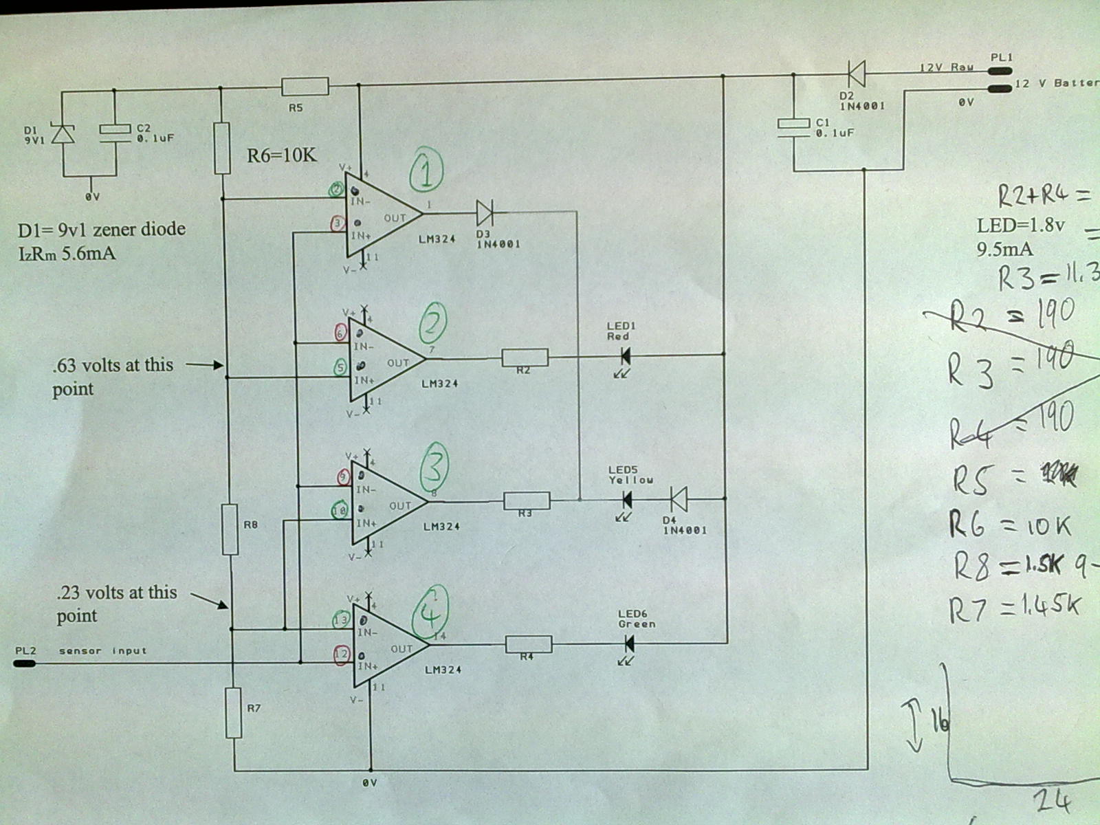
A 12V power supply is connected to the positive terminal, allowing current to flow through a protection diode and a capacitor that smooths the voltage. A zener resistor (R5) limits the current to the zener diode, which regulates the...
Warning: include(partials/cookie-banner.php): Failed to open stream: Permission denied in /var/www/html/nextgr/view-circuit.php on line 713
Warning: include(): Failed opening 'partials/cookie-banner.php' for inclusion (include_path='.:/usr/share/php') in /var/www/html/nextgr/view-circuit.php on line 713