
220v LED DIMMER

The circuit in question likely utilizes a phase control method for dimming, which is a common technique for adjusting the brightness of LED bulbs operating at high voltage levels such as 220V. This method involves controlling the amount of power delivered to the load (in this case, the LED bulbs) by altering the phase of the AC waveform.
A typical dimmer circuit for 220V LED bulbs may consist of several key components: a triac, an opto-isolator, a zero-crossing detector, and a variable resistor (potentiometer). The triac acts as a switch that can be turned on and off at specific points in the AC cycle, allowing for the control of the power delivered to the LED bulbs. The opto-isolator provides electrical isolation between the high-voltage side and the control side of the circuit, ensuring safety and preventing damage to low-voltage components.
The zero-crossing detector is crucial for ensuring that the triac is triggered at the appropriate moment in the AC cycle, which minimizes electrical noise and reduces the risk of flickering in the LED bulbs. The potentiometer allows the user to adjust the resistance, thereby varying the phase angle at which the triac is triggered and enabling smooth dimming of the connected LED bulbs.
It is important to note that not all LED bulbs are compatible with dimming circuits; therefore, it is advisable to use LED bulbs specifically designed for dimming applications to achieve optimal performance. Additionally, the circuit design should be verified for compliance with electrical safety standards to ensure reliable and safe operation when connected to high voltage.Hi everyone! I found this circuit in my computer (i don`t remember where i got it and when) and i was wandering if it`s able to dim 220V LED BULBS? it .. 🔗 External reference
Related Circuits
The bi-directional sequencer employs a 4-bit binary up/down counter (CD4516) and two "1 of 8 line decoders" (74HC138 or 74HCT138) to produce the widely recognized Nigh. The bi-directional sequencer circuit is designed to manage the sequencing of outputs based on...
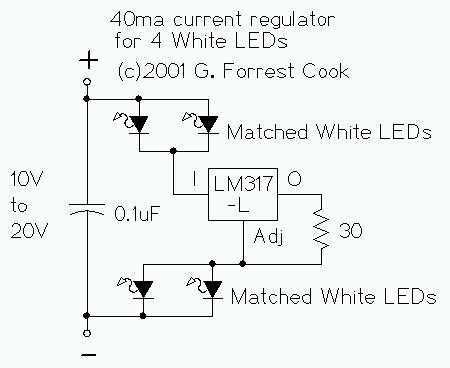
The LM317L and resistor act as a current regulator set to 40ma. Current flows from the battery through one pair of LEDs, through the regulator, through the other pair of LEDs, and back to the battery. The capacitor filters...
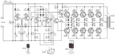
The step-up section of this inverter circuit utilizes a transformer with a 12V center-tapped (CT) secondary and a primary winding designed for 0 to 220V. The operating frequency is established by a flip-flop configured to 50 Hz. The inverter circuit...
LED displays consist of arrays of Light Emitting Diodes (LEDs) arranged in various shapes to convey specific information. The operation of LED displays is similar to that of standard LEDs, requiring straightforward connections when sufficient microcontroller pins are available....
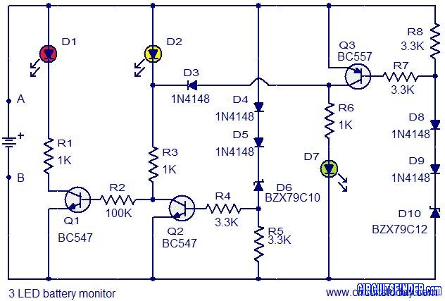
This is the circuit diagram of a 3 LED bar graph type battery monitor circuit that is ideal for monitoring the voltage level of an automobile battery. When battery voltage is 11.5V or less, transistor Q1 will be on...
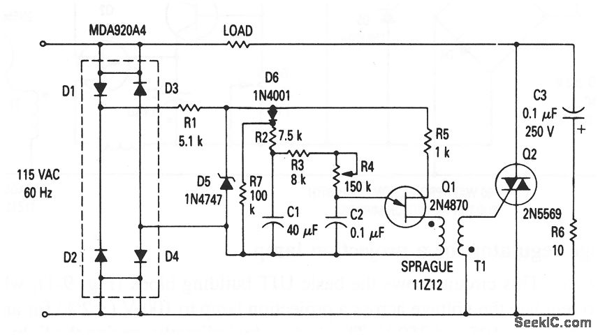
This circuit illustrates the fundamental UJT building block, utilized in a light dimmer with soft-start functionality. It gradually applies current to the light, effectively minimizing high surges (high inrush current) that typically occur in cold-filament light dimmers, which can...