
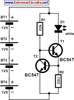
Regulated LED Lamp

The described circuit utilizes an LM317L voltage regulator configured as a constant current source to drive two pairs of Light Emitting Diodes (LEDs). The LM317L is selected for its ability to provide a stable output current, which is set to approximately 40 mA using an appropriate resistor. The resistor value can be calculated using the formula \( I = \frac{1.25V}{R} \), where \( I \) is the desired current and \( R \) is the resistor value in ohms.
In this configuration, current flows from a power source, such as a battery, through the first pair of matched LEDs. The LEDs must be matched in terms of forward voltage drop and current rating to ensure equal current distribution and prevent any one LED from being overdriven, which could lead to failure. After passing through the first pair of LEDs, the current then flows through the LM317L, which regulates the current, maintaining it at the set value of 40 mA. The current then continues to the second pair of matched LEDs and returns to the battery.
A capacitor is included in the circuit to filter out noise from the power supply lines, enhancing the stability of the current supplied to the LEDs. This capacitor should be placed as close as possible to the power supply pins of the LM317L to effectively dampen any high-frequency noise.
To achieve better current balance among the four LEDs, small resistors can be added in series with each LED. This practice helps to equalize the voltage drops across each LED, compensating for any slight variations in their forward voltage characteristics. However, introducing these additional resistors increases the components count and may complicate the circuit design.
Overall, this current regulation circuit is suitable for applications requiring stable LED illumination, ensuring longevity and consistent performance of the LEDs while minimizing the risk of thermal runaway or unequal current distribution. Proper thermal management of the LM317L should also be considered, especially if the circuit operates for extended periods or at higher ambient temperatures.The LM317L and resistor act as a current regulator set to 40ma. Current flows from the battery through one pair of LEDs, through the regulator, through the other pair of LEDs, and back to the battery. The capacitor filters out noise on the power supply lines. The LED pairs must be matched so that the current through them is roughly equivalent. Small resistors could be placed in series with each of the four LEDs to improve the balance, but the parts count would go way up.
🔗 External reference
Related Circuits
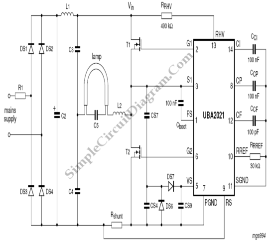
The UBA2021 can be utilized as a 600 V lamp controller and half-bridge driver integrated circuit (IC) for high-power applications. It is designed for long-life compact fluorescent lamp (CFL) and tubular fluorescent lamp (TL) applications. The UBA2021 is a versatile...
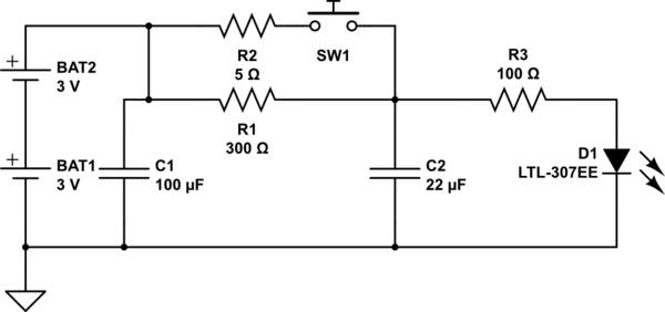
The circuit operates as follows: The LED is typically powered at a low brightness through resistors R1 and R3. SW1 functions as a spring and wire-based accelerometer. When SW1 is activated, capacitor C2 charges rapidly at a rate determined...
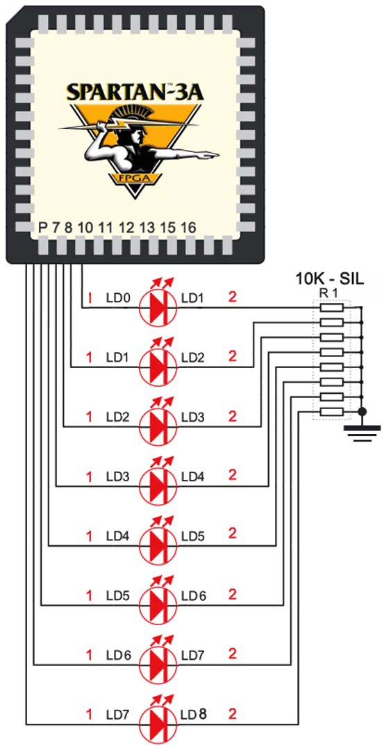
The Spartan-3an board features eight LEDs connected to FPGA I/O pins. The cathode of each LED is connected to ground through a 330-ohm resistor. To illuminate a specific LED, the corresponding FPGA control signal must be set to High. The...
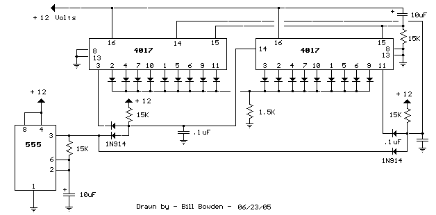
When power is applied, the 15K resistor and 10µF capacitor at pin 15 will reset the counters to a zero count, with pin 3 at +12V and all other outputs at zero. The two diodes (1N914) and a 15Ω...
IC4, C1, R1 and R2 are used for the clock pulse which is fed to both the counters IC2 and IC3 Pin 14. IC1 is a Flip Flop and is used as a switch to enable either IC2 or...
Physicians and repair engineers frequently utilize small light pens for visual examination purposes. Although these pens are rugged and can be expensive, their vulnerability lies in the bulb, which is a replaceable component. In practice, this often translates to...