
220V Power Line Interface
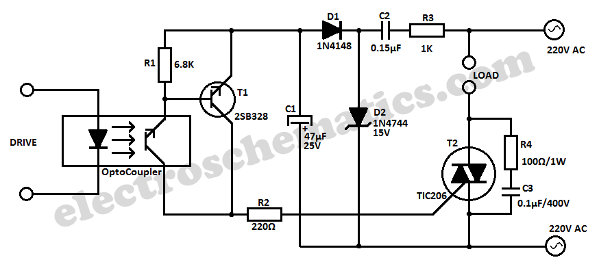
This 220V power interface circuit serves as an effective tool for monitoring electrical devices while ensuring safety through galvanic isolation. The optocoupler, specifically the TIL111, is integral to the design, providing necessary isolation between high voltage AC lines and low voltage digital systems. The circuit's design allows for direct monitoring of the device's AC power line, which simplifies the integration process for various devices without requiring modifications to the circuit.
The resistor R1 is crucial for limiting the current flowing through the optocoupler's LED, ensuring it operates within safe parameters. The choice of a 0.5 mA current helps to optimize the performance of the optocoupler while maintaining sufficient brightness for the LED to trigger the phototransistor effectively. Diode D1's role in rectifying the current is essential for converting the AC signal into a usable form for the optocoupler, allowing it to function correctly even in the presence of AC voltage fluctuations.
The output from the optocoupler's phototransistor can be connected to a microcontroller or a computer interface, enabling the monitoring system to detect the on/off status of the connected device. The use of capacitor C1 is also noteworthy; it smooths out any ripples in the output current, providing a stable signal for further processing. However, in applications where the detection of rapid changes in the on/off status is required, removing C1 can allow the system to respond more quickly to these changes.
Overall, this circuit design is well-suited for applications in industrial and home automation systems where monitoring of electrical devices is necessary, providing both safety and efficiency in operation.This simple 220V power interface is intended as an interface for monitoring electric equipments and devices using a computer. The interface only senses whether the device being monitored is turned on or off. The most important aspect of the circuit is the galvanic isolation between the AC main line being monitored and the interface to the computer
. This is done with the use of the optocoupler IC TIL111 but a suitable replacement can be used too. To avoid having to modify the circuit for each device being monitored, the circuit monitors the device`s AC power line directly. The resistor R1 lets a current of around 0. 5 mA through the optocoupler LED. The other half of the current is rectified through the diode D1. It is obvious that the current to the optocoupler LED is half wave rectified. This means that the phototransistor part of the optocoupler receives only light impulses of around 100uA.
The capacitor C1 filters out the current pulsation and maintains a smooth output current. In case the current pulsation is needed, just remove C1. 🔗 External reference
Related Circuits
The W7800 is a positive integrated voltage regulator, while the F007 consists of an operational amplifier used in a power supply tracking application circuit. Some configurations utilize both positive and negative power supplies, with a negative supply necessary to...
This circuit is designed to indicate the power output level of any audio amplifier. It is simple, portable, and displays three power levels that can be adjusted to any desired value. The circuit operates by measuring the output voltage from...
Using this circuit you can convert the 12V dc into the 220V AC. In this circuit, 4047 is used to generate the square wave of 50Hz and amplify the current and then amplify the voltage by using the step...
Application of the High Power LED Driver SP7652 with an Analog 0V-to-10V dimmer. Electrical Requirements: Input Voltage of 5.5V to 28V, Output Voltage VF of LED, Output Current ranging from 0 to 6A. This circuit is designed to provide...
The design is based on the TubeHobby and serves as the power supply used in their NC2. This kit was constructed as an initial project involving nixie tubes, and a review of this excellent kit can be found in...

A simple lab power supply electronic project can be designed using this circuit diagram, which is based on the LM2576 monolithic integrated regulator that provides all the active functions for a step-down (buck) switching regulator. As seen in the...
Warning: include(partials/cookie-banner.php): Failed to open stream: Permission denied in /var/www/html/nextgr/view-circuit.php on line 713
Warning: include(): Failed opening 'partials/cookie-banner.php' for inclusion (include_path='.:/usr/share/php') in /var/www/html/nextgr/view-circuit.php on line 713