
lm2576 simple lab power supply electronic project

The LM2576 is a versatile and efficient voltage regulator, ideal for applications requiring a stable output voltage from a higher input voltage. This integrated circuit is designed to deliver up to 3A of output current with a voltage drop of up to 40V, making it suitable for various power supply applications.
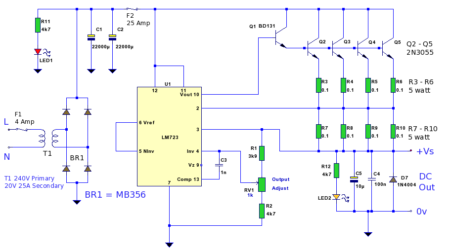
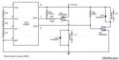
In the circuit configuration, the input voltage is connected to the input pin of the LM2576. An unregulated DC voltage source, typically around 40 volts, is recommended to ensure the regulator operates within its specified range. The output voltage can be adjusted by using external resistors connected to the feedback pin, allowing for output voltage settings between 1.23V and 37V.
The circuit also includes several essential passive components. An input capacitor (C1) is used to filter the input voltage, reducing voltage spikes and noise. A larger output capacitor (C2) is placed at the output to stabilize the output voltage and minimize ripple. Additionally, an inductor (L1) is crucial for the buck conversion process, storing energy when the switch is on and releasing it to the load when the switch is off.
To enhance performance, a diode (D1) is incorporated to prevent backflow of current and protect the circuit from potential damage. It is important to select a Schottky diode for its low forward voltage drop and fast switching characteristics.
Thermal management should also be considered, as the LM2576 may generate heat during operation. A heat sink may be necessary to dissipate excess heat, especially when operating at higher currents.
In summary, this simple lab power supply circuit utilizing the LM2576 provides an effective solution for converting higher DC voltages to stable, lower output voltages suitable for various electronic applications. The design's simplicity and efficiency make it an ideal choice for educational purposes and practical implementations in laboratory settings.A simple lab power supply electronic project can be designed using this circuit diagram which is based on the LM2576 monolithic integrated regulator that provide all the active functions for a step-down (buck) switching regulator. As you can see in the schematic circuit this LM2576 power supply require few external electronic components and an in
put unregulated dc voltage of about 40 volts. 🔗 External reference
Related Circuits
This audio amplifier design employs two LM3886 chips per channel in a parallel configuration, based on the PA100 parallel amplifier detailed in National Semiconductor's application note AN1192. It can deliver approximately 50W into an 8-ohm speaker and 100W into...
This circuit is a simple and cost-effective design that utilizes an operational amplifier IC 741 (IC1) alongside a push-pull amplifier made with transistors for signal amplification. The project name indicates its intended application, which includes level control in hydroponic...
A 12 Volt high current 20 Amp power supply. The output voltage is variable from 12.2 Volt to 14.4V, allowing it to be set for any device requiring voltage and current within that range. This power supply unit (PSU)...
In this circuit, a 74HC14 hex Schmitt trigger inverter functions as a square wave oscillator to drive a small signal transistor configured as a class C amplifier. The oscillator frequency can be set to a fixed value using a...
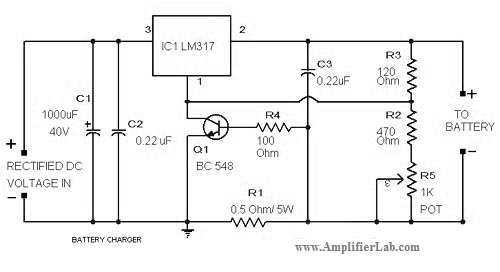
The circuit diagram of a lead-acid battery charger is presented here. The main component of this circuit is the IC LM317. The lead-acid battery charger circuit utilizing the LM317 voltage regulator is designed to efficiently charge lead-acid batteries while providing...
Circuit stereo TDA2822 audio power amplifier circuit schematics. In this series, the TDA2822M IC is utilized as the primary amplifier. Additionally, alternatives such as KA2209 and NJM2073 can also be employed. The TDA2822 audio power amplifier circuit is designed to...
Warning: include(partials/cookie-banner.php): Failed to open stream: Permission denied in /var/www/html/nextgr/view-circuit.php on line 713
Warning: include(): Failed opening 'partials/cookie-banner.php' for inclusion (include_path='.:/usr/share/php') in /var/www/html/nextgr/view-circuit.php on line 713