
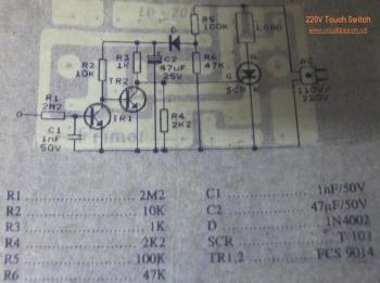
220V Touch Switch
This touch dimmer circuit operates on 220V AC and offers a user-friendly interface for adjusting the brightness of incandescent lamps. The core component, the TT8486A or TT6061A CMOS IC, facilitates the touch-sensitive control, making it ideal for modern applications where mechanical switches may be impractical. The design eliminates the need for physical buttons, reducing wear and enhancing durability, particularly in environments prone to moisture or dust.
The circuit's operation begins when the mains power is activated. The touch sensor detects the user's input and sends a signal to the IC, which processes the command and adjusts the output to the connected lamp. The three-stage dimming feature is accomplished through the use of a triac and diac, enabling smooth transitions between brightness levels. The inclusion of an RFI noise suppression circuit is critical for maintaining the integrity of the electrical system, minimizing electromagnetic interference that could affect nearby devices.
In addition to its primary function as a dimmer, this circuit can also be adapted for controlling the speed of AC motors, making it versatile for various applications. The schematic diagram provides a clear representation of the component layout and interconnections, ensuring ease of assembly for individuals with basic electronics knowledge. The components listed, including resistors, capacitors, diodes, and transistors, are standard and readily available, contributing to the overall cost-effectiveness of the project.
The tachometer schematic adds another layer of functionality, allowing for the measurement of frequency through a proportional current output. This feature is particularly useful in automotive applications where monitoring engine speed is essential. The connection points for the high-voltage input ensure accurate readings, reinforcing the circuit's reliability in practical use. Overall, this circuit represents a comprehensive solution for both lighting control and frequency measurement in electrical systems.Here the 220V AC lamp touch dimmer circuit. By only touching this touch dimmer you are able to increase the light intensity of incandescent lamps in three stages. The touch dimmer is designed all around 8-pin CMOS IC TT8486A/TT6061A especially produced for touch dimmer applications.
In the beginning, when mains switch is "on", the lamp. Turn on a nd turn off your electrical devices using touch switch, so you can "play" your electronic devices more fun. :). Touch switch don`t need mechanical part, so they will not worn out due to mechanical contact. Touch switches can be used in places where regular switches would not last, such as wet or. This is a 220V LED flasher circuit which is intended as a reliable replacement to thermally-activated switches used for Christmas tree lamp-flashing.
This a cheap circuit and easy to build. Schematic diagram: Component Parts: R1_ 100K R2, R5_ 1K R3, R6_ 470R R4_ 12K C1_ 1000 µF 25V D1-D4_ 1N4007 D5_ SCR P0102D Q1_ BC327 Q2_ BC337 SK1_. This simple 220V light dimmer circuit can be used to adjust the brightness of mains lights. It also can be used to adjust the speed of AC motors. It uses a triac, diac and has a radio-frequency interference (RFI) noise suppression circuit built into it as well.
Schematic diagram: Component part: R1 = 10K R2. Here is a simple Tachometer schematic. The basis of the frequency converter circuit-current, which converts the input signal into a proportional current measured pointer device. Deflection milliammeter proportion to the frequency input signal. To install the device on input pin A car should be connected to high voltage wire and pin B - to the.
🔗 External reference
Related Circuits

An AC mains operated single LED flasher circuit is constructed using the widely utilized CMOS timer chip TLC555. The entire circuit is powered directly from the 230VAC grid supply via a capacitive potential divider and associated components. This compact...

The game was originally designed to position three balls locked in holes on a slowly rotating ring around the Deadworld. Once the third ball was secured, a mechanical arm would release them, dropping the balls onto the playfield. This...

An AC-DC power supply without a power switching circuit is typically utilized for lighting load circuits. Once the power grid is restored, the standby power supply automatically switches on. An automatic switching circuit using a transistor is implemented, with...

The inverter circuit features the CMOS 4047 as its primary component, converting a 12V DC voltage to a 220V AC voltage. The 4047 operates as an astable multivibrator. A symmetrical rectangular signal is generated at pins 10 and 11,...

Tasks such as jewel cutting and polishing require workers to repeatedly turn on and off two electrical appliances in succession for different services on the same workpiece. This process can be cumbersome, as it demands full concentration on the...
A switch that is controlled by its ambient temperature operates without human intervention, except during the assembly of the electronic thermostat. This thermally controlled switch has numerous practical applications. For instance, if the internal temperature of a computer rises...