
220V Flashing LED Circuit

The circuit operates on the principle of utilizing the TLC555 timer in an astable configuration, which allows it to generate a continuous square wave output. The timing components, R2, R3, and C3, are critical in setting the frequency of the oscillation, which can be adjusted by varying these component values. The capacitive potential divider is an essential part of the design, as it reduces the high AC voltage from the mains supply to a lower level suitable for the operation of the TLC555.
The red LED (D5) serves as the visual indicator in this circuit, flashing at a frequency determined by the timer. The reverse mode operation means that the LED is connected in such a way that it receives current when the output of the timer goes high, creating a flashing effect. Resistor R4 is crucial in preventing excessive current from damaging the LED and ensuring the longevity of the circuit.
In practical applications, this LED flasher circuit can be used in various settings where visibility is important, such as safety markers on roads or as indicators for switches in dimly lit areas. The compact size of the circuit allows for easy integration into existing structures or devices, making it a versatile solution for enhancing visibility and safety.AC mains operated single LED flasher circuit, built using the popular CMOS timer chip TLC555 is shown below. The whole circuit is powered directly by the grid supply of 230VAC through a capacitive potential divider and associated components.
This minuscule Power LED Flashing circuit can be easily fit inside a very small plastic enclosure. The 220V flashing led circuit can be incorporated into a roadside/parking ground lane marker bollard, or used as a warning for other obstacles such as fences, scaffolding tubes, etc. It can also be suspended from light/fan switch pull-cords to make them easy to find in the dark. IC1 is here wired as a low frequency free-running oscillator, whose frequency is determined by the values of timing components R2, R3 and C3.
With the values and configuration shown, IC1 works like a narrow pulse width square wave oscillator source, giving very short positive pulses at its output pin3. Note that, IC1 is used to drive a 10mm red LED (D5) in reverse (ie sinking) mode. Resistor R4 limits the current flow through D5 and hence, through IC1. 🔗 External reference
Related Circuits

This is one of many available variations for a Symmetrical SRPP Preamplifier based on the 6DJ8 / ECC88 family of tubes. The SRPP circuit has also been referred to as a SEPP, Totem Pole, Mu Follower, Mu amplifier, and...

The oscillator circuit consists of a 1MHz quartz crystal resonator and a NAND gate, with the output buffer stage provided by NAND gate 3. This circuit can be utilized for calibrating standard frequency. The described oscillator circuit operates at a...

This is a discrete high-current switch-mode LED driver circuit. The fundamental principle of this circuit is based on the buck-converter topology. The efficiency of this circuit is 80%. The discrete high-current switch-mode LED driver circuit utilizes a buck converter configuration...

A simple transistor generator and transformer converts a 1.5V battery voltage to several hundred volts. This high voltage current then passes through a diode, which rectifies the current to DC. This DC current is stored in a relatively large...

The following circuit illustrates a 20 dB VHF amplifier circuit diagram utilizing the BF197 transistor. Features include a simple circuit design. The 20 dB VHF amplifier circuit is designed to amplify very high frequency signals, making it suitable for applications...
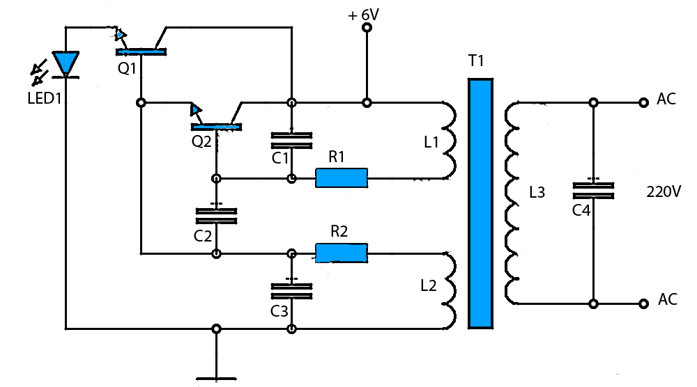
The circuit schematic presented is a voltage inverter circuit that converts a 6-volt DC input into a 220-volt AC output. It is designed to deliver a maximum output power of 30 watts and operates with a low input current....