
24 Watt Audio Amplifier
The 24 watt amplifier circuit is designed to provide efficient audio amplification while maintaining a compact form factor. This amplifier is suitable for various applications, including automotive audio systems, home theater setups, and computer audio enhancements. The circuit operates optimally with 4-ohm speakers, ensuring maximum power transfer and sound quality. However, it is also compatible with 8-ohm speakers, albeit with slightly reduced output power.
The amplifier's design incorporates a power supply that consumes approximately 60 watts to deliver the desired 24 watts of output power. This indicates a relatively efficient design, but it also results in significant heat generation, approximately 28 watts. To manage this thermal output, the use of a robust heatsink is essential. The heatsink must be designed to dissipate heat effectively, allowing the amplifier to operate within safe temperature limits while ensuring it remains cool enough to touch.
Key components of the circuit may include an operational amplifier or a dedicated audio amplifier IC, along with passive components such as resistors, capacitors, and possibly inductors to filter and stabilize the audio signal. The layout of these components should be carefully considered to minimize signal interference and maximize performance. Additionally, the power supply design should be capable of delivering stable voltage and current to prevent distortion during operation.
Overall, this amplifier circuit represents an economical and efficient solution for enhancing audio systems across various platforms, providing users with a reliable means to achieve high-quality sound reproduction.The 24 watt amp is easy to build, and very inexpensive. The circuit can be used as a booster in a car audio system, an amp for satellite speakers in a surround sound or home theater system, or as an amp for computer speakers. The circuit is quite compact and uses only about 60 watts. 1. The circuit works best with 4 ohm speakers, but 8 ohm units will do. 2. The circuit dissipates roughly 28 watts of heat, so a good heatsink is necessary. The chip should run cool enough to touch with the proper heatsink installed. 3. The circuit 🔗 External reference
Related Circuits
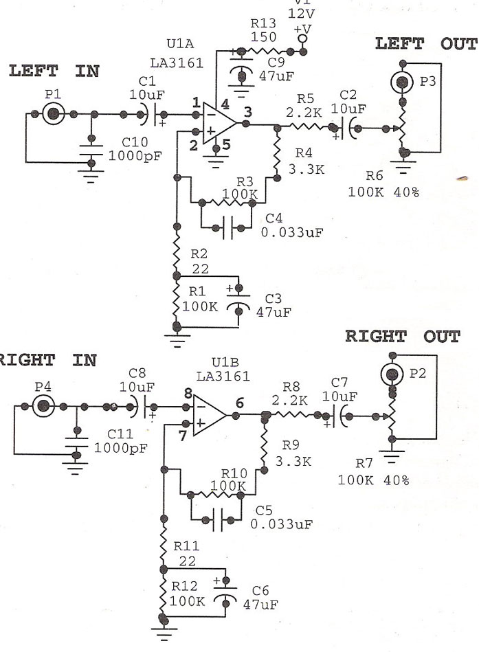
Preamplifier with LA3161. Preamplifiers are utilized to amplify low-level signals, such as those from microphones and tape heads, before they are sent to power amplifiers. The LA3161 is a versatile integrated circuit designed for use in audio preamplification applications. It...
If 40 watts RMS from 20Hz to 30KHz +/-1.5 dB is appealing, this experiment may be of interest. A significant issue with public address equipment is the use of audio output transformers that lack sufficient iron to manage lower...
Phonographs are becoming increasingly rare as they are being replaced by more advanced audio systems such as CD players, recorders, and portable MiniDisc player/recorders. This shift is acknowledged by audio equipment manufacturers, leading to the omission of traditional phono...
The CXG1024N is a high-power antenna switch MMIC designed to connect a transmitter/receiver (TX/RX) to one of four antennas. This integrated circuit (IC) is fabricated using Sony's GaAs J-FET process and operates with a single positive power supply. The CXG1024N...
This circuit is a diagram of a mini amplifier. The amplifier circuit has a power output of 10 watts and is well-suited for car audio applications. It utilizes the TDA2009A integrated circuit as the power amplifier. To prevent excessive...
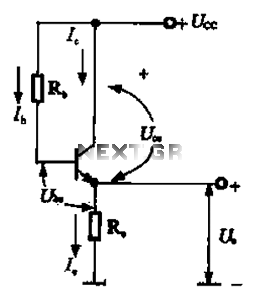
A common collector amplifier can be analyzed through its DC and AC paths, as illustrated in Figure 1-14. The DC path is responsible for providing a biasing circuit for the power transistor, determining whether the transistor is in an...