
10 Watt Stereo Amplifier Circuit Using TDA2009A
The mini amplifier circuit described operates at a power output of 10 watts, making it an efficient choice for car audio systems where space and power conservation are critical. The TDA2009A is a versatile integrated circuit known for its robustness and reliability in audio amplification applications. It is capable of driving speakers directly, making it ideal for automotive environments.
In the schematic, the TDA2009A is typically connected to a power supply that provides the necessary voltage, often in the range of 12V to 14.4V, which is standard for automotive electrical systems. The circuit may include input capacitors for signal coupling, resistors for gain adjustment, and feedback components to stabilize the amplifier's performance.
To manage heat dissipation effectively, a heat sink is employed, attached to the TDA2009A to ensure that the IC operates within safe temperature limits. The use of a thermal compound between the IC and the heat sink enhances thermal conductivity, allowing for efficient heat transfer and preventing thermal overload that could lead to circuit failure.
Additional features may include a low-pass filter at the output to reduce high-frequency noise, ensuring a cleaner audio signal. The circuit may also incorporate protection mechanisms such as fuses or thermal shutdown features to safeguard against short circuits or excessive current draw.
Overall, this mini amplifier circuit is designed for simplicity and effectiveness, making it an excellent choice for enhancing audio quality in automotive applications. Proper layout and component selection are crucial for achieving optimal performance and reliability.This circuit is a circuit diagram mini amplifer. This amplifier circuit has a power of 10 watts. This amplifier circuit is very suitable to apply to your car audio. This amplifier using IC TDA2009A, as amplifeir power. To avoid excessive heat in the IC using some heat sink compound between the heat sink . 🔗 External reference
Related Circuits
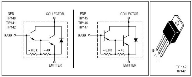
This is an economical 150 Watt amplifier circuit featuring two Darlington power transistors, TIP 142 and TIP 147. The circuit is capable of delivering up to 150 W RMS to a 4 Ohm speaker, providing substantial audio output. The...
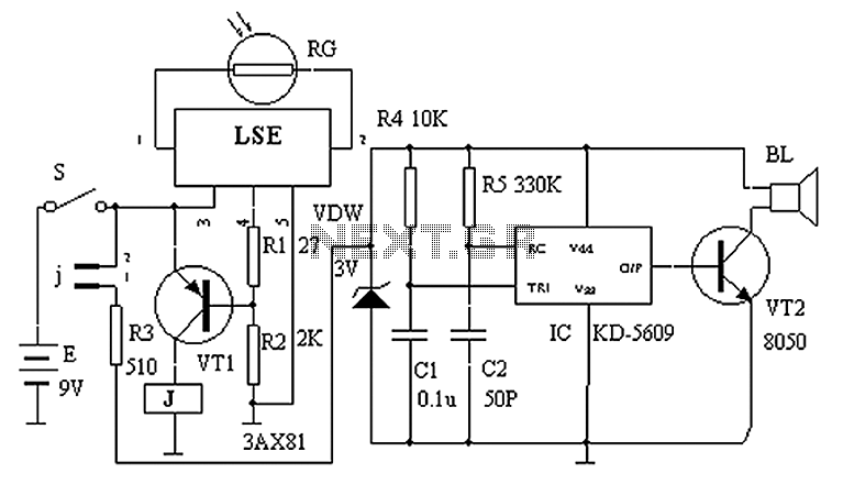
The circuit principle is illustrated in the accompanying figure. When the night light shines on the photosensitive resistor RG, it exhibits a high resistance (significantly greater than 50K). As a result, the output of the LSE pin is low,...

The schematic for this project is designed to be very simple, utilizing a minimal number of components to keep costs and assembly time low. The primary components in the schematic include the PIC 18F452 microcontroller, a tilt sensor, and...
The circuit below illustrates generating a single positive pulse which is delayed relative to the trigger input time. The circuit is similar to the one above but employs two stages so that both the pulse width and delay can...
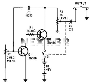
Useful for troubleshooting audio, video, and lower frequency RF amplifiers. This circuit generates a signal that is rich in harmonics. The circuit designed for troubleshooting audio, video, and lower frequency RF amplifiers is crucial for diagnosing issues in these systems....
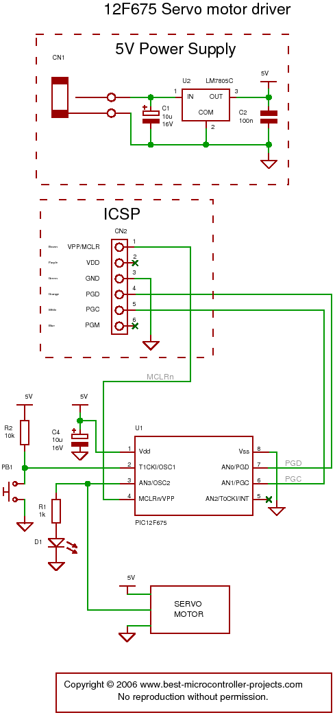
The following circuit illustrates a servo motor driver. This circuit is based on the 12F675 IC. Features include Timer 0 timing and a single control line. The servo motor driver circuit utilizing the 12F675 integrated circuit (IC) is designed to...
Warning: include(partials/cookie-banner.php): Failed to open stream: Permission denied in /var/www/html/nextgr/view-circuit.php on line 713
Warning: include(): Failed opening 'partials/cookie-banner.php' for inclusion (include_path='.:/usr/share/php') in /var/www/html/nextgr/view-circuit.php on line 713